Concrete structure box, plate and joist combined beam

A technology for concrete structures and composite beams, applied in bridges, bridge materials, bridge construction, etc., can solve the problems of uneconomical engineering, weak lateral torsional rigidity, and bulky appearance of beams, so as to improve the efficiency of cross-section use, durable and reliable appearance , The effect of saving engineering materials

Active Publication Date: 2013-12-04
四川西南交大土木工程设计有限公司
View PDF4 Cites 1 Cited by
  • Summary
  • Abstract
  • Description
  • Claims
  • Application Information

AI Technical Summary

Problems solved by technology

[0003] However, in the beam structure subject to the huge concentrated force in the mid-span, the traditional concrete box-section beam will face the following problems: In order to resist the increased bending moment in the mid-span, it is necessary to increase the height of the beam body section as a whole, but this will make the beam The use efficiency of the body section is greatly reduced, and at the same time, it will also make the appearance of the beam body larger, and at the same time increase the layout of prestressed steel tendons, and these materials are used to resist the weight of the beam body itself to a large extent, which will bring serious engineering problems. Uneconomical
[0004] The traditional truss girder form will face the following problems: the truss structural members mainly bear axial force, and the transverse torsional rigidity is weak, and due to the existence of tension members, steel is usually used, and the compression members of steel trusses buckling
Therefore, when encountering a relatively large concentrated force, its compression members usually dominate the bridge design, and the size is very large, resulting in a sharp increase in steel consumption
At the same time, its cumbersome appearance also restricts the application of truss structure.
[0005] Therefore, the existing technology has been difficult to overcome the problem of the huge concentrated force transmission in the mid-span of the beam body

Method used


Image

  • Concrete structure box, plate and joist combined beam
  • Concrete structure box, plate and joist combined beam
  • Concrete structure box, plate and joist combined beam

Examples


Embodiment Construction

[0015] The present invention will be further described below in conjunction with the accompanying drawings and embodiments.

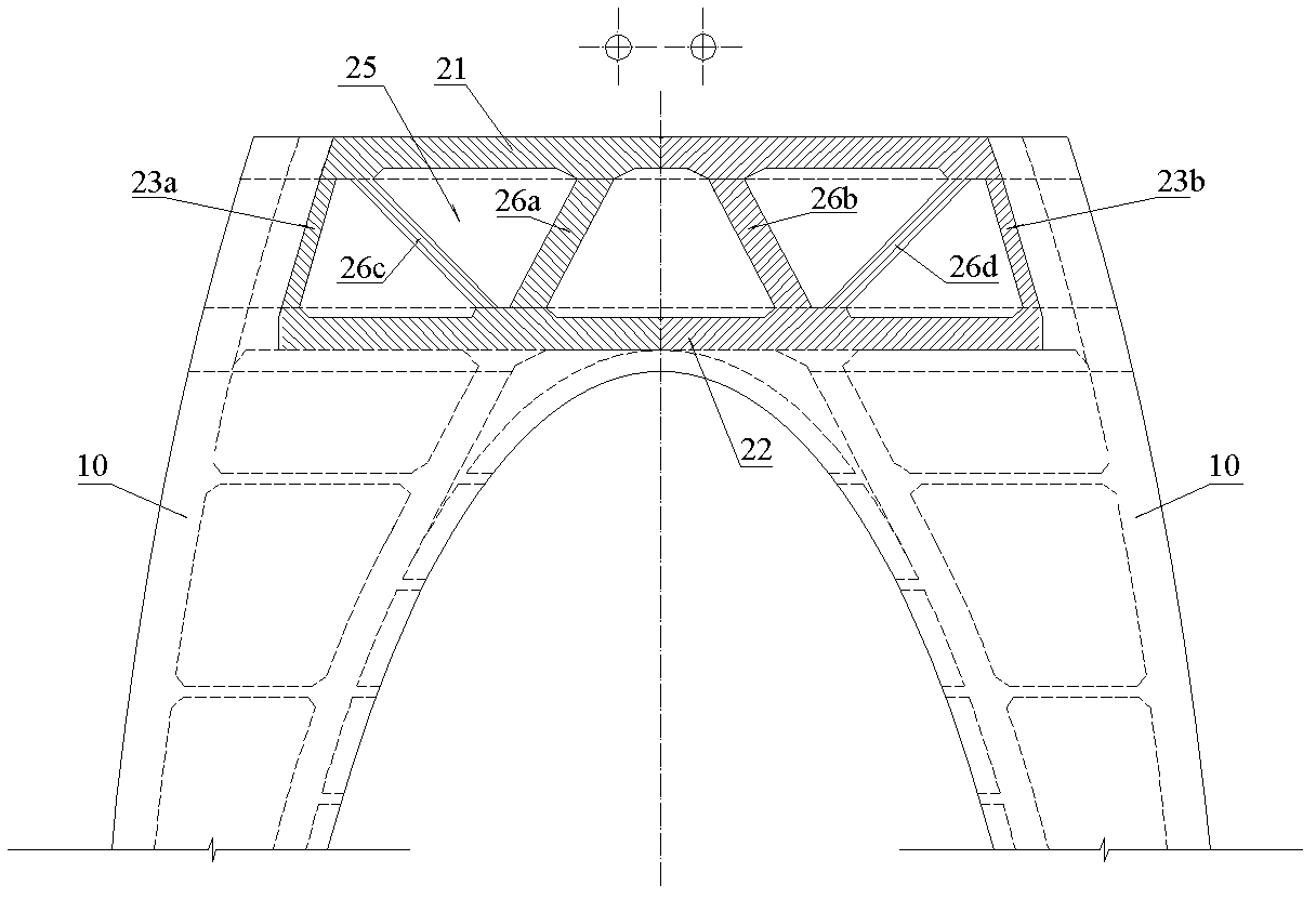
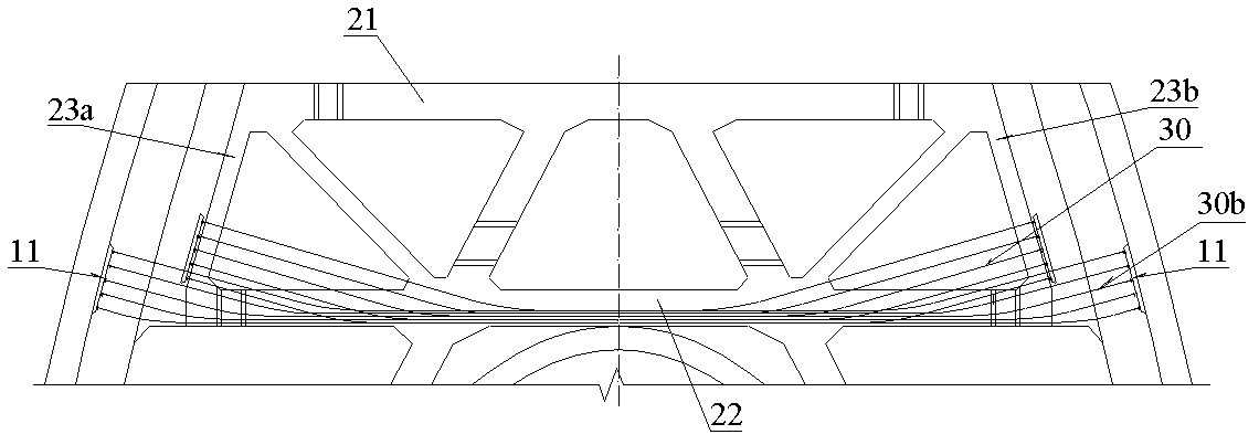
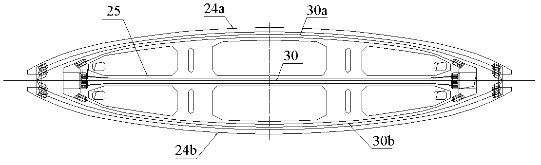
[0016] refer to figure 1 with image 3 , a concrete structure box slab truss composite beam, including a box-shaped beam integrated with the load-bearing body 10, the box-shaped beam includes a top plate 21, a bottom plate 22, two ends of the diaphragm 23a, 23b and two sides of the web 24a, 24b. The inner space of the box-shaped beam is provided with a middle web 25 and inclined transverse partitions arranged in pairs, and the inclined transverse diaphragm and the middle web 25, top plate 21, and bottom plate 22 form a truss, wherein the middle web 25 is connected with the top plate 21 and the bottom plate 22 It is consolidated with the transverse diaphragms 23a and 23b at both ends, and the inclined transverse diaphragm is consolidated with the top plate 21, the bottom plate 22, the middle web 25 and the webs 24a and 24b on both sides.

[0017] refer...


PUM


Abstract

A concrete structure box, plate and joist combined beam aims to transmit great concentration power and evenly disperse the concentration power onto a load-carrying member and meanwhile do not increase the construction cost excessively. The concrete structure box comprises a box-shaped cross beam fixedly connected to be a whole with a bearing body (10), and the box-shaped cross beam comprises a top plate (21), a bottom plate (22), two end diaphragm plates (23 a and 23 b), and two side webs (24a and 24 b). The concrete structure box, plate and joist combined beam is characterized in that a middle web (25) and inclined diaphragm plates in pair are arranged in the interior space of the box-shaped cross beam, the inclined diaphragm plates, a middle web (25), a top plate (21), and a bottom plate (22) form a truss frame, the middle web (25) is fixedly connected with the top plate (21), the bottom plate (22) and the two end diaphragm plates (23a and 23 b), and the inclined diaphragm plates are fixedly connected with the top plate (21), the bottom plate (22), the middle web (25) and the two side webs (24a and 24 b); and a pre-stress steel strand is configured in the bottom plate (22).

Description

technical field [0001] The invention relates to bridges, in particular to a concrete structure box plate truss composite beam. Background technique [0002] Box-section beams have good force-bearing advantages, such as high section torsional rigidity, roof and bottom plates can effectively resist positive and negative bending moments, and can combine load-bearing structures and force-transmitting structures to jointly bear forces, and the section utilization rate is high. Economical and practical, with mature construction methods and strong adaptability, it has been widely used in various structures. [0003] However, in the beam structure subject to a large mid-span concentrated force, the traditional concrete box-section girder will face the following problems: In order to resist the increased bending moment at the mid-span, it is necessary to increase the height of the beam body section as a whole, but this will make the beam The use efficiency of the body section is gre...

Claims


Application Information

Patent Timeline
Patent Type & Authority Patents(China)
IPC IPC(8): E01D2/04E01D101/28
Inventor 谢尚英郑爱华任清顺
Owner 四川西南交大土木工程设计有限公司
Why Eureka
Try Eureka