Multi-bit convolution punching/tamping engineering groover

A multi-bit and slotting machine technology, applied in drilling equipment, earth-moving drilling, driving devices for rotary combined drilling, etc., can solve the problems of unsatisfactory efficiency, energy consumption and economy, and achieve good market prospects Crafty, high-stable effects

Inactive Publication Date: 2013-12-18
JIANGSU TELONG DRIVESHAFT MFG +2
View PDF1 Cites 5 Cited by
  • Summary
  • Abstract
  • Description
  • Claims
  • Application Information

AI Technical Summary

Problems solved by technology

[0010] To sum up, from the current situation, various domestic and foreign machines for constructing underground diaphragm walls are respectively suitable for certain strata, but generally only suitable for soil layers or sandy gravel layers and relatively weak weathered rock layers. For hard rock layers Even the most advanced equipment in the world is not ideal in terms of efficacy, energy consumption and economy. However, in fact, engineering practice often encounters a complex formation that changes with depth, which is an urgent problem to be solved

Method used


Image

  • Multi-bit convolution punching/tamping engineering groover
  • Multi-bit convolution punching/tamping engineering groover
  • Multi-bit convolution punching/tamping engineering groover

Examples


Embodiment 1

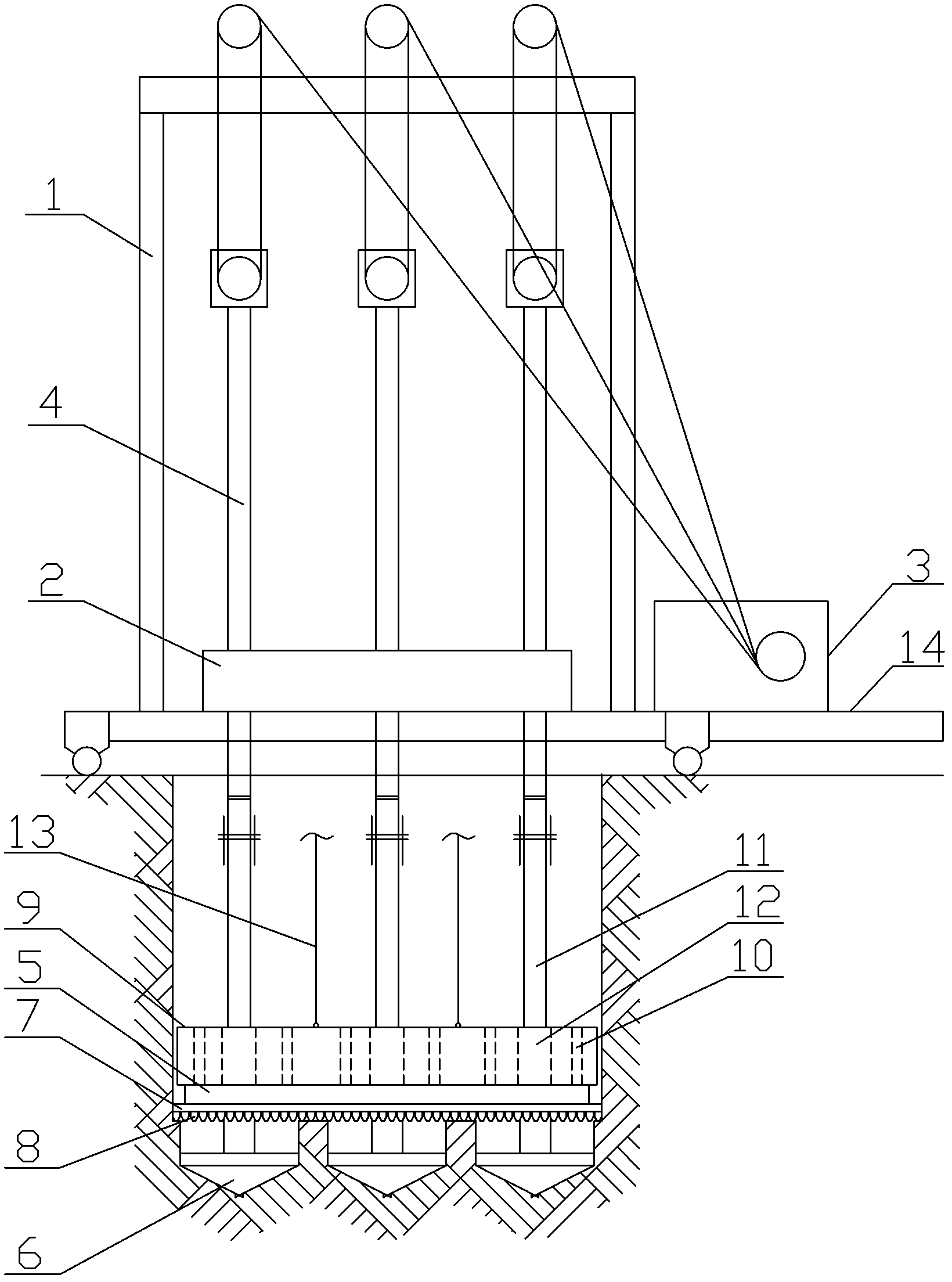
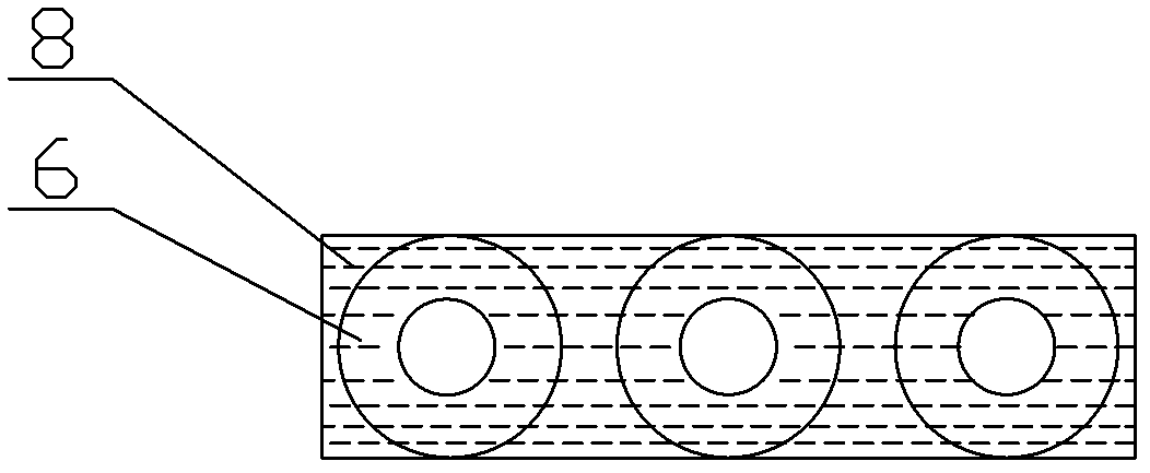
[0035] Such as figure 1 As shown, the multi-bit rotary punching engineering slotting machine of this embodiment consists of: frame 1, gearbox 2, hoisting equipment 3, control equipment (not shown in the figure), sewage device (not shown in the figure) , the gearbox 2 is fixed to the frame 1, and the slotting machine of this project also includes 3 stroke drill rods 4 symmetrically arranged, and a positioning beam 5, and the lower part of the positioning beam 5 is provided with 3 fixed beams fixed with the positioning beam in the vertical direction. The connected main drill bit 6 driven by the stroke drill rod can be used for gyrating motion. The lower end surface of the positioning beam 5 is fixed with a knife row seat 7, and the knife row seat 7 is provided with a knife row 8 with an alloy cutter head. There is a punching hammer 9 that can move up and down and can transmit the impact force to the positioning beam 5, the main drill bit 6 and the knife row 8.

[0036] Such as ...

Embodiment 2

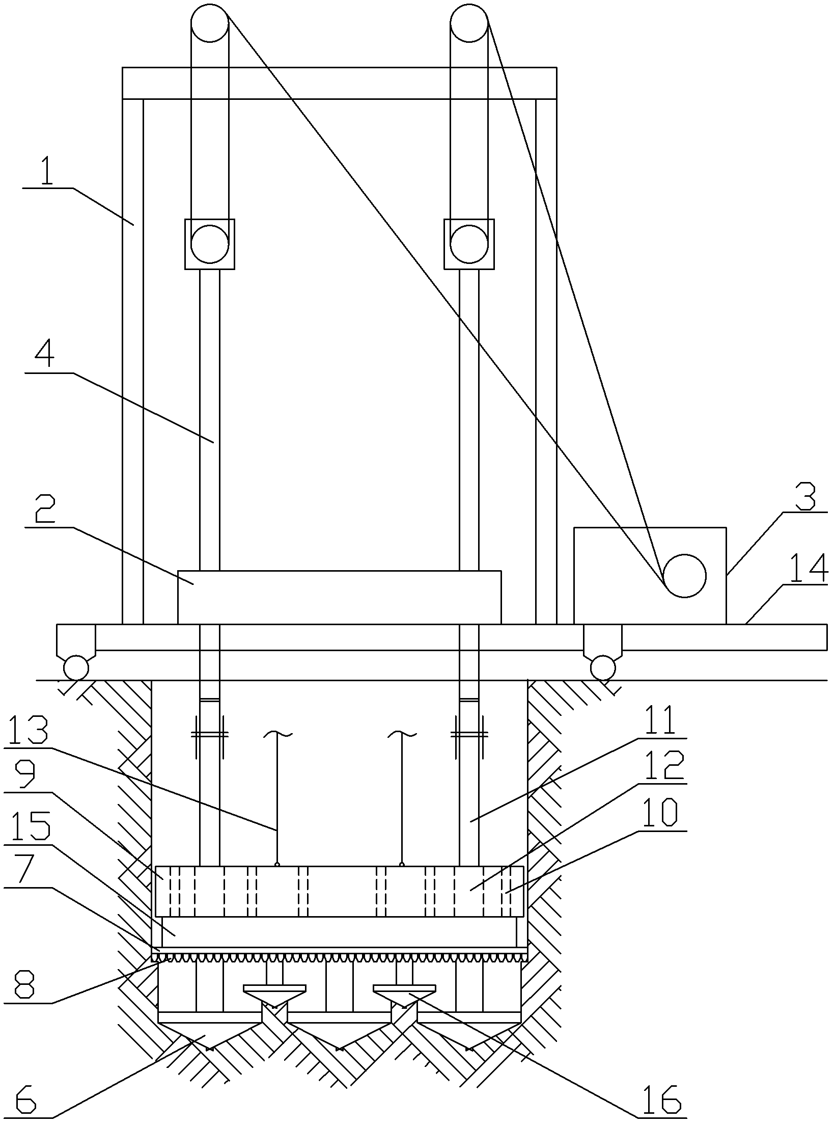
[0040] Such as image 3 As shown, the multi-bit rotary punching engineering slotting machine of this embodiment consists of: frame 1, gearbox 2, hoisting equipment 3, control equipment (not shown in the figure), and sewage device (not shown in the figure) , the gearbox 2 is fixed to the frame 1, and the slotting machine of this project also includes 22 stroke drill rods 4 symmetrically arranged, and a split head case 15 with a variable speed transmission mechanism (not shown in the figure), and the split head The lower part of the casing 15 is provided with some main drill bits 6 and auxiliary drill bits 16 that are fixedly connected with the transfer head casing 15 in the vertical direction, and the main drill bits 6 and auxiliary drill bits 16 are distributed in a cross-symmetric manner successively. 1. The auxiliary drill bit 16 is linked by the speed change transmission mechanism inside the transfer head case 15, the stroke drill rod 4 is connected with the drill rod 11 co...


PUM


Abstract

The invention discloses a multi-bit convolution punching / tamping engineering groover which comprises symmetrically-arranged stroke drill pipes and a positioning beam, wherein the lower part of the positioning beam is provided with a main drill bit which can make convolution motion driven by the stroke drill pipes, a tool array seat is fixed on the lower end face of the positioning beam and provided with a tool array with alloy tool tips, and a punching / tamping hammer which can move up and down is arranged above the positioning beam. Under the punching and tamping actions of the punching / tamping hammer, the main drill bit drills rock soil to form a plurality of drill holes, and the surplus rock soil is broken by the tool array through the punching and tamping actions of the punching / tamping hammer. By using the groover disclosed by the invention, a groove can be formed at a time, and the wall of the formed groove is smooth and neat, therefore, the construction requirements are completely satisfied, and the performance index of the groover disclosed by the invention completely exceeds that of groovers of the same kind. The groover disclosed by the invention carries out drilling, punching and tamping simultaneously by using multiple drill bits and the punching / tamping hammer; and the operating state of the groover is adjusted according to the mechanical properties of rock soils of stratums, i.e. for soft stratums, an drilling is mainly performed, for hard stratums, punching is mainly performed, and for ultrahard stratums, tamping is mainly performed, thereby efficiently directly completing grooving on complex stratums.

Description

technical field [0001] The invention relates to a basic engineering construction machine, in particular to a slotting machine for multi-drill rotary punching and smashing engineering. Background technique [0002] In water conservancy, transportation, construction and other engineering fields, it is necessary to build various underground continuous walls under different geological conditions. However, it is still a very difficult and urgent problem to open deep grooves on hard rock formations to build various underground continuous walls. The problem. [0003] Recalling that the relevant domestic units have done a lot of work in the construction technology of the underground diaphragm wall, and have made some progress, mainly using the following equipment and technology: [0004] 1. Water-jet underground wall-forming technology: the main principle is to use large-flow, high-pressure water jets to punch the soil layer, cut through the blade at the bottom of the trough-formin...

Claims


Application Information

Patent Timeline
Patent Type & Authority Patents(China)
IPC IPC(8): E21B6/00
Inventor 万泽仁刘农
Owner JIANGSU TELONG DRIVESHAFT MFG
Why Eureka
Try Eureka