Worm drive

A technology of worm drive and worm shaft, which is applied in hoisting devices, portable lifting devices, components with teeth, etc., and can solve problems such as increased expansion/contraction and difficulty in maintaining backlash

Inactive Publication Date: 2012-04-11
JTEKT CORP
View PDF6 Cites 7 Cited by
  • Summary
  • Abstract
  • Description
  • Claims
  • Application Information

AI Technical Summary

Problems solved by technology

However, in the case of increasing the thickness of the synthetic resin member 104 whose coefficient of linear expansion is higher than that of metal, the amount of expansion / contraction of the synthetic resin member 104 caused by temperature changes increases.
In this case, it is difficult to keep the backlash amount between the tooth portion 104a of the synthetic resin member 104 and the tooth portion 101a of the worm shaft 101 at an appropriate value.

Method used


Image

  • Worm drive
  • Worm drive
  • Worm drive

Examples


Embodiment Construction

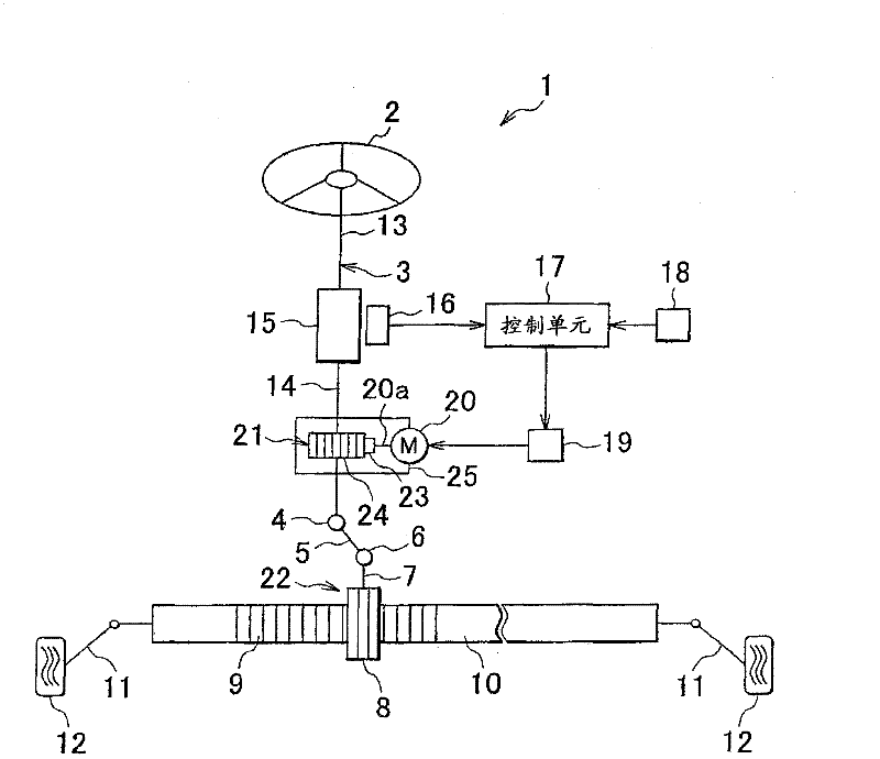
[0022] Preferred embodiments of the present invention will be described below with reference to the accompanying drawings. figure 1 is a schematic diagram showing a schematic configuration of the electric power steering apparatus 1 according to the first embodiment of the present invention. see figure 1 , the electric power steering apparatus 1 has: a steering shaft 3 connected to a steering member 2 such as a steering wheel; an intermediate shaft 5 connected to the steering shaft 3 through a universal joint 4; a pinion shaft 7 connected to the intermediate shaft 5 through a universal joint 6 ; and the rack shaft 10 . The rack shaft 10 forms a rack 9 that meshes with a pinion 8 provided at the distal end of the pinion shaft 7 and extends in the left-right direction of the vehicle.

[0023] Rods 11 are connected to respective ends of the rack shaft 10, and each tie rod 11 is connected to a corresponding steering wheel 12 through a corresponding joint arm (not shown in the fig...


PUM


Abstract

A worm wheel (24) of a worm drive (21) includes an annular synthetic resin member (56) having tooth portions (56a) meshing with a worm shaft (23) and a core (55) having an outside diameter portion (61) joined to an inside diameter portion (58) of the synthetic resin member (56). The outside diameter portion (61) of the core (55) has first joining tooth portions (64) that protrude outward in a radial direction (R1) and are joined to the inside diameter portion (58) of the synthetic resin member (56). Each of the first joining tooth portions (64) includes a widening portion (64b) whose width in a circumferential direction (C1) increases toward the outside in the radial direction (R1).

Description

technical field [0001] The invention relates to a worm drive. Background technique [0002] Electric power steering equipment is usually provided with a worm gear to transmit the output of the electric motor to the steering mechanism. For example, in Japanese Patent Application Laid-Open No. 2006-194296 (JP-A-2006-194296), a worm transmission includes a worm shaft connected to an electric motor and a worm wheel connected to a steering shaft. Fig. 6 shows a schematic configuration of a worm drive 100 similar to that described in JP-A-2006-194296, which shows a section perpendicular to the central axis of the worm wheel (see JP-A-2006- 194296, paragraphs [0029] and [0030] and Figures 7 and 8). Referring to FIG. 6 , a worm shaft 101 is made of metal, and a worm wheel 102 is composed of an annular metal core 103 connected to a steering shaft or the like and a synthetic resin member 104 surrounding the outer circumference of the core 103 . On the outer circumference of the syn...

Claims


Application Information

Patent Timeline
Patent Type & Authority Applications(China)
IPC IPC(8): F16H55/24F16H55/08
CPCF16H55/22F16H55/06F16H2055/065Y10T74/19828
Inventor 菊地新
Owner JTEKT CORP
Why Eureka
Try Eureka