Device and method for measuring magnetic declination of permanent magnet
A technology of measuring device and measuring method, which is applied in the direction of the magnitude/direction of the magnetic field, can solve the problems of inability to measure the magnetic declination of permanent magnets, etc., and achieve the effects of improving measurement efficiency and simplifying measurement methods
Active Publication Date: 2012-04-11
SOUTHWEST INST OF APPLIED MAGNETICS
View PDF8 Cites 9 Cited by
- Summary
- Abstract
- Description
- Claims
- Application Information
AI Technical Summary
Problems solved by technology
[0003] In order to solve the problems in the prior art, the present invention provides a permanent magnet magnetic declination measurement device and method, which solves the problem that the magnetic declination of permanent magnets with various shapes and easy magnetization direction is magnetized in a single direction cannot be measured.
Method used
View moreImage
Smart ImageViewing Examples
Examples
Embodiment 2
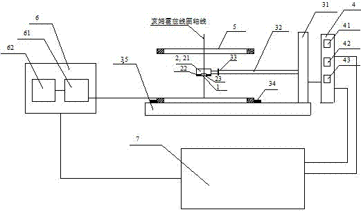
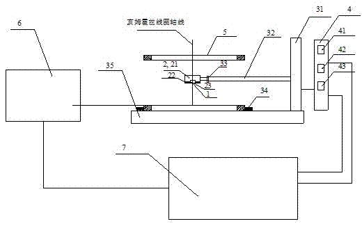
[0043] Embodiment 2, refer to figure 2 , image 3 As shown, the induced voltage detection and processing unit 6 in this embodiment is a digital fluxmeter, the input terminal of the digital fluxmeter is connected to the output terminal of the Helmholtz coil 5 , and its output terminal is connected to the computer control and processing unit 7 . Other structures are the same as in Embodiment 1.
Login to View More PUM
 Abstract
The invention relates to the field of anisotropic permanent magnet measurement, and discloses a device for measuring magnetic declination of a permanent magnet. The device consists of a loading platform (2), a displacement platform (3), a multidimensional electric control device (4), an induced voltage generation unit (5), an induced voltage detection and processing unit (6) and a computer control and processing unit (7). The device provided by the invention can be used for measuring the magnetic declinations of various shapes of the permanent magnets with single easy magnetization direction;and by adopting the device, the measuring method is simplified, and the measuring efficiency is improved.
Description
technical field [0001] The invention relates to the field of anisotropic permanent magnet measurement, in particular to a permanent magnet magnetic declination measurement device and method. Background technique [0002] During the magnetic field orientation forming process of anisotropic permanent magnet materials, the orientation direction of the product is not parallel to the direction of the orientation magnetic field, resulting in a magnetic declination; A magnetic declination is generated between the axes. The existence of the declination angle of the permanent magnet causes the magnetic field to be generated in the non-magnetized direction of the magnet, forming a stray magnetic field. At present, there are limitations in domestic patents on magnetic declination measurement. CN101382586A invention patent is about the measuring device and method for the orientation degree of circular axially magnetized permanent magnets, and CN101833074A is also about the declination ...
Claims
Login to View More Application Information
Patent Timeline
 IPC IPC(8): G01R33/02
Inventor 程玲莉张明王敬东沈安国李忭谭福明
Owner SOUTHWEST INST OF APPLIED MAGNETICS
Features
- R&D
- Intellectual Property
- Life Sciences
- Materials
- Tech Scout
- Unparalleled Data Quality
- Higher Quality Content
- 60% Fewer Hallucinations
Learn More Browse by: Latest US Patents, China's latest patents, Technical Efficacy Thesaurus, Application Domain, Technology Topic, Popular Technical Reports.
© 2025 PatSnap. All rights reserved.Legal|Privacy policy|Modern Slavery Act Transparency Statement|Sitemap|About US| Contact US: help@patsnap.com


