
Pixel structure and driving method thereof

A technology of pixel structure and driving method, applied in nonlinear optics, instruments, optics, etc., can solve the problem of loss of aperture ratio of pixel structure, and achieve the effect of reducing color shift

Active Publication Date: 2014-06-04
AU OPTRONICS CORP
View PDF4 Cites 1 Cited by
  • Summary
  • Abstract
  • Description
  • Claims
  • Application Information

AI Technical Summary

Problems solved by technology

[0005] The present invention provides a pixel structure and its driving method, which can solve the known problem of losing the aperture ratio of the pixel structure when a single pixel electrode is divided into main pixel electrodes and sub-pixel electrodes.

Method used


Image

  • Pixel structure and driving method thereof
  • Pixel structure and driving method thereof
  • Pixel structure and driving method thereof

Examples


Embodiment Construction

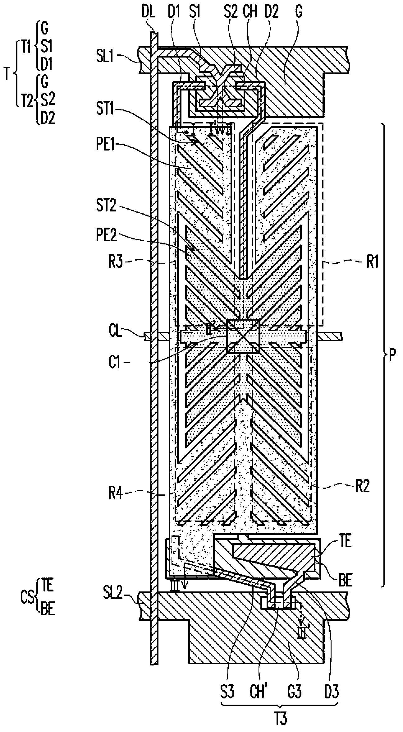
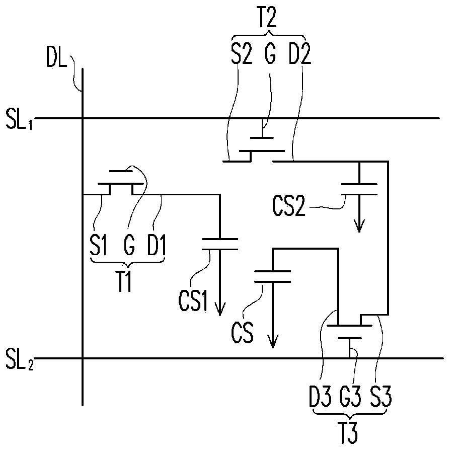
[0023] figure 1 is a schematic top view of a pixel structure according to an embodiment of the present invention. figure 2 is along figure 1 The cross-sectional schematic diagram of the section line I-I', the section line II-II', and the section line III-III'. image 3 yes figure 1 The equivalent circuit diagram of the pixel structure. Please refer to figure 1 , figure 2 as well as image 3 , the pixel structure of this embodiment is arranged on the substrate 100, which includes the first scanning line SL1, the second scanning line SL2, the data line DL, the driving element T, the first pixel electrode PE1, the insulating layer 104, the second pixel electrode PE2 and shared switching element T3.

[0024] The material of the substrate 100 can be glass, quartz, organic polymer, or opaque / reflective material (for example: conductive material, metal, wafer, ceramic, or other applicable materials), or other applicable materials .

[0025] The first scan line SL1 , the se...


PUM


Abstract

A pixel structure includes a scan line, a data line, a driving device, a first pixel electrode, an insulating layer and a second pixel electrode. The driving device is electrically connected to the scan line and the data line. The first pixel electrode is electrically connected to the driving device. The insulating layer covers the first pixel electrode. The second pixel electrode is disposed on the insulating layer. The second pixel electrode is electrically connected to the driving device and is not directly connected to or not contacted with the first pixel electrode.

Description

technical field [0001] The present invention relates to a pixel structure and its driving method, and in particular to a pixel structure capable of reducing the color washout phenomenon of a display and its driving method. Background technique [0002] Nowadays, the performance requirements for liquid crystal displays in the market are developed towards high contrast, fast response and wide viewing angle. Currently, the technologies that can meet the wide viewing angle requirements include Multi-domain Vertical Alignment (MVA), Multi-Domain Horizontal Alignment (MHA), etc. ), twisted nematic plus viewing angle expansion film (TN+film) and transverse electric field form (IPS). Although the liquid crystal display with the technologies listed above can achieve the purpose of wide viewing angle, there is still much room for improvement in the existing color washout phenomenon. [0003] Generally speaking, the so-called color shift means that when the user watches the image disp...

Claims


Application Information

Patent Timeline
Patent Type & Authority Patents(China)
IPC IPC(8): G02F1/1362G02F1/1368G02F1/133G09G3/36
CPCG02F1/134309G02F2001/134345G02F2201/40G02F1/133345G02F1/13624G02F1/134345
Inventor 廖培钧徐文浩王惠珺
Owner AU OPTRONICS CORP
Learn More