
Powder control structure of novel printer

A printer and powder control technology, which is applied in electrography, optics, instruments, etc., can solve the problems of light printing, blackness attenuation, bottom dust, etc., and achieve the effect of stable powder control

Inactive Publication Date: 2012-04-11
ZHUHAI BENMA PRINTMAX IMAGINE
View PDF5 Cites 2 Cited by
  • Summary
  • Abstract
  • Description
  • Claims
  • Application Information

AI Technical Summary

Benefits of technology

This patented technology helps improve image quality by controllably charging toners onto paper during printing without causing damage or affecting its appearance. It involves placing an elastomeric material called a support plate near one end of a tin roll containing magnetic particles for better stability against wear caused by high-speed rotation. When the printer starts up, there're also another spring system made from steel wires attached at both ends. These springs help keep the developer inside stable while still allowing them to move freely around within their cylindrical space.

Problems solved by technology

This patented technical problem addressed during Jump Development for Laser Printers involves improving the performance of the developer system without affecting other important factors like color reproduction or resolution capabilities. Specifically, current methods have limitations in achieving stable and consistently low levels of residual magnetism after multiple cycles of turning off power supply.

Method used


Image

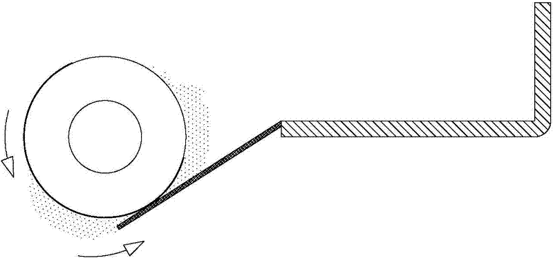
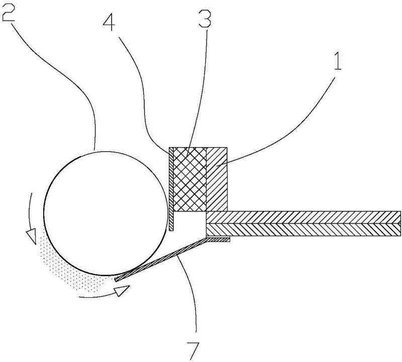
  • Powder control structure of novel printer
  • Powder control structure of novel printer
  • Powder control structure of novel printer

Examples


Embodiment Construction

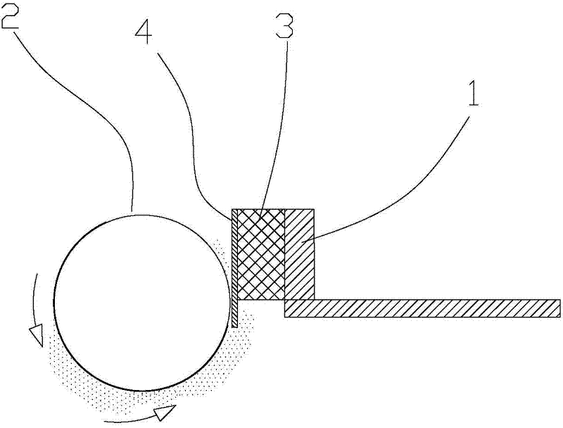
[0025] refer to figure 2 , the invention discloses a novel powder control structure for printers, which includes a supporting member 1 arranged in the toner cartridge and a metal friction member 4 in contact with the developing element 2, and an elastic Institution 3.

[0026] Such as figure 2 As shown, in this first specific embodiment, the metal friction member 4 is a metal sheet, and the elastic mechanism 3 is a rubber layer. Through the extrusion of the rubber layer, the charged carbon powder can form a uniform layer on the surface of the aluminum tube. layer, so that the powder control is stable, and the elasticity of the rubber layer can keep the friction between the metal sheet and the carbon powder within an appropriate range. In order to achieve convenient installation, the metal sheet is combined with the rubber layer by pasting, but the above-mentioned installation method does not constitute a limitation to the present invention. The above-mentioned structure ca...


PUM


Abstract

The invention discloses a powder control structure of a novel printer, which comprises a supporting member, a metal friction piece connected with a development element in a toner cartridge, an elastic mechanism is provided between the supporting member and the metal friction piece, when the printer works, powdered carbon absorbed on the surface of an aluminum pipe carries higher electrified quantity through the friction of the metal friction piece, an uniform layer of electrified powdered carbon can be formed on the surface of the aluminum pipe through extrusion effect of the elastic mechanism, thereby the stabilization of powder control can be realized. The powdered carbon with the above structure effect has characteristics of higher electrified quantity and stable powder control, so that the problems of light printing color, decreased blackness and bottom ash caused by insufficient electrified quantity of powdered carbon can be avoided.

Description


Claims


Application Information

Patent Timeline
Owner ZHUHAI BENMA PRINTMAX IMAGINE
Learn More