

Catalytic heat carrier for pyrolysis of carbonaceous material and preparation method thereof
A technology for pyrolysis of carbon and carrier, which is applied in the methods of granulating raw materials, materials for heat exchange, chemical instruments and methods, etc. Carriers, waste of energy, etc.
- Summary
- Abstract
- Description
- Claims
- Application Information
AI Technical Summary
Problems solved by technology
Method used
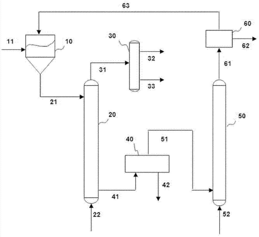
Image

Examples
Embodiment 1
[0100] The combustion bottom ash of the coal direct liquefaction residue and the waste coal direct liquefaction catalyst were mixed at a weight mixing ratio of 2:1. The chemical composition of the mixture was shown in Table 1. The mixture was wet ground to a particle size of about 30 μm.
[0101] Table 1
[0102] SiO 2
[0103] Mix 10kg of the above mixture with 18.5kg of a mixture of alumina sol and silica sol with a weight mixing ratio of 1:3 to prepare a slurry. The pH of the sol mixture is 2 to 3, and the obtained mixture is continuously and uniformly stirred. Slurry for 30 minutes, and then spray-dry the obtained homogeneous mixture slurry to prepare catalytic heat carrier porous particles with a particle size ranging from 50 to 200 μm. The spray-dried catalytic heat carrier particles were sintered at 700°C for 4 hours. The specific surface area of the sintered catalytic heat carrier porous particles is 250-400m 2 / g, the pore size ranges from 2 to 20nm. ...
Embodiment 2
[0125] The waste fluidized catalytic cracking catalyst, the combustion bottom ash of the direct coal liquefaction residue and the waste coal direct liquefaction catalyst are mixed in a weight mixing ratio of 1:2:1, wherein the embodiment 2 uses the coal direct liquefaction residue used in the embodiment 1 Combustion bottom ash and waste coal direct liquefaction catalyst, some element compositions of the spent fluid catalytic cracking catalyst are shown in Table 7 below, and the mixture was wet ground to a particle size of about 30 μm.
[0126] Table 7
[0127] Ni
V
Fe
Cu
C
0.3-0.7%
0.3-1.2%
1.1-1.6%
0.1-0.5%
0.3-1.0%
[0128] Mix 10kg of the above mixture with 19kg of a mixture of alumina sol and silica sol with a weight mixing ratio of 1:3 to prepare a slurry. The pH value of the sol mixture is about 2 to 3, and the above slurry is stirred continuously and uniformly After 30 minutes, the homogeneous mixture...
PUM
| Property | Measurement | Unit |
|---|---|---|
| Particle size | aaaaa | aaaaa |
| Specific surface area | aaaaa | aaaaa |
| Aperture | aaaaa | aaaaa |
Abstract
Description
Claims
Application Information