
Infrared touch screen adopting longitudinally arranged optoelectronic elements

A technology of infrared touch screen and photoelectric components, applied in the direction of electrical digital data processing, input/output process of data processing, instruments, etc., can solve problems such as low scanning accuracy, slow response, and non-response to touch, so as to improve scanning accuracy and improve Quality, touch responsive effects

Inactive Publication Date: 2012-04-11
上海优熠电子科技有限公司
View PDF0 Cites 1 Cited by
  • Summary
  • Abstract
  • Description
  • Claims
  • Application Information

AI Technical Summary

Problems solved by technology

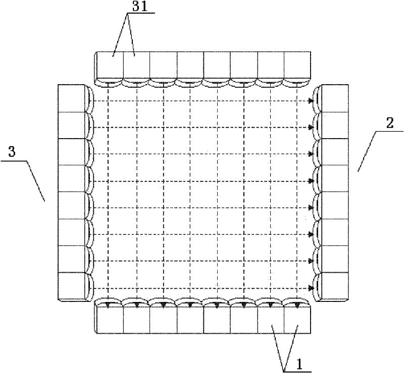
refer to figure 1 , the infrared emitting device is formed by a number of infrared light sources 31 arranged horizontally, and the distance between the light-emitting points of two adjacent infrared light sources 31 is in the range of 5 mm to 6 mm. This distance is relatively long, resulting in low scanning accuracy.
When the finger touches the touch panel, the photosensitive element of the infrared receiving device is not easy to feel the light weakening, causing problems such as no response or slow response to the touch, and affecting the quality of the infrared touch screen

Method used


Image

  • Infrared touch screen adopting longitudinally arranged optoelectronic elements
  • Infrared touch screen adopting longitudinally arranged optoelectronic elements
  • Infrared touch screen adopting longitudinally arranged optoelectronic elements

Examples


Embodiment Construction

[0016] In order to make the technical means, creative features, goals and effects achieved by the present invention easy to understand, the present invention will be further described below in conjunction with specific diagrams.

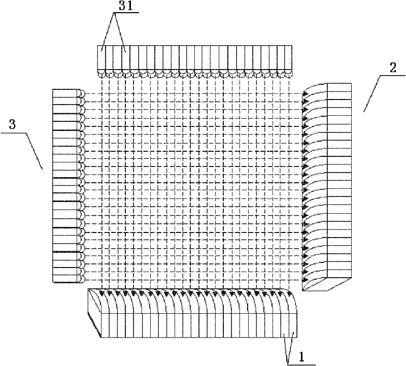
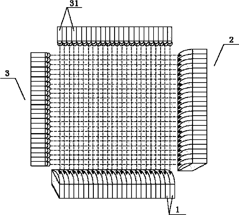
[0017] refer to figure 2 An infrared touch screen adopting vertically arranged photoelectric elements includes a touch panel, an infrared emitting device, and an infrared receiving device. The infrared emitting device includes an infrared emitting array 3 that emits infrared light. The infrared emitting array 3 includes at least two infrared Diode 31. The infrared diodes 31 are flat, the width of the infrared diodes 31 is greater than their thickness, and at least two infrared diodes 31 are arranged along the thickness direction. Compared with the traditional columnar infrared diodes 31 arranged in the thickness direction, the distance between the light-emitting points of two adjacent infrared diodes 31 is greatly shortened, which helps to improve ...


PUM


Abstract

The invention relates to a touch screen, in particular to an infrared touch screen. The infrared touch screen adopting longitudinally arranged optoelectronic elements comprises a touchpad, an infrared transmitting device and an infrared receiving device, wherein the infrared receiving device comprises an infrared receiving array; the infrared transmitting device comprises an infrared transmitting array; the infrared transmitting array comprises at least two infrared diodes which are arranged into a column; the infrared diode is flat; the width of the infrared diode is greater than the thickness of the infrared diode; and the at least two infrared diodes are arranged along a thickness direction. Due to the adoption of the technical scheme, the infrared touch screen has the advantages of improving scanning accuracy, quickening touch response and the like, and the quality of the infrared touch screen adopting the longitudinally arranged optoelectronic elements is effectively improved.

Description

technical field [0001] The invention relates to a touch screen, in particular to an infrared touch screen. Background technique [0002] The infrared touch screen uses the dense infrared matrix in the X and Y directions to detect and locate the user's touch. The infrared touch screen is to install a touch panel in front of the display, and the four sides of the touch panel are arranged with infrared emitting devices and infrared receiving devices, which correspond to an infrared matrix that crosses horizontally and vertically. When the user touches the screen, the finger will block the horizontal and vertical infrared rays passing through the position, and then the position of the touch point on the screen can be judged. refer to figure 1 , the infrared emitting device is formed by a plurality of infrared light sources 31 arranged horizontally, and the distance between the light-emitting points of two adjacent infrared light sources 31 is in the range of 5 mm to 6 mm. This...

Claims


Application Information

Patent Timeline
Patent Type & Authority Applications(China)
IPC IPC(8): G06F3/042
Inventor 何怡程抒一袁正朱天堃
Owner 上海优熠电子科技有限公司
Learn More