
Illumination lamp with uniform illuminance

A technology of uniform illuminance and lighting lamps, applied in lighting devices, fixed lighting devices, lighting auxiliary devices, etc., can solve the problems of inflexible adjustment of the lighting area of ​​the lamp head, difficulty in assembly and maintenance of the lamp head, and increase in the manufacturing cost of the lamp head, etc., to avoid The effect of uneven lighting, improved lighting brightness, and easy installation

Inactive Publication Date: 2012-04-18
林万炯
View PDF6 Cites 2 Cited by
  • Summary
  • Abstract
  • Description
  • Claims
  • Application Information

AI Technical Summary

Problems solved by technology

[0003] In the prior art, in order to improve the defect of LED uneven illumination, if there is a Chinese invention patent "A LED Lamp Holder" with application number CN201110002480.1, it provides such an LED lamp holder, which includes an LED lamp tube, an LED light source, The LED seat on which the LED light source is installed and a group of lenses in front of the LED light source focus and emit the light emitted by the LED light source to obtain uniformly distributed output light. The group of lenses includes: the closest The first lens of the LED light source is used to diffuse the light emitted by the LED light source; the second lens located behind the first lens is used to disperse and focus the light passing through the first lens again; and a third lens arranged behind the second lens, for re-dispersing and focusing the light passing through the second lens
The LED lamp head in the above-mentioned patent uses a set of lenses located in front of the LED light source to process the light emitted by the LED light source, thereby obtaining evenly distributed light spots. However, the realization structure of the above-mentioned patent is relatively complicated and needs to be installed Three lenses not only need to increase the internal volume of the lamp cap, but also increase the manufacturing cost of the lamp cap, and bring certain difficulties to the assembly and maintenance of the lamp cap; Limitation, the irradiation range is restricted by the light emitting angle of the lens itself, and the lighting area of ​​the lamp head cannot be flexibly adjusted as the height of the illuminated object increases

Method used


Image

  • Illumination lamp with uniform illuminance
  • Illumination lamp with uniform illuminance
  • Illumination lamp with uniform illuminance

Examples


Embodiment Construction

[0022] The present invention will be further described in detail below in conjunction with the accompanying drawings and embodiments.

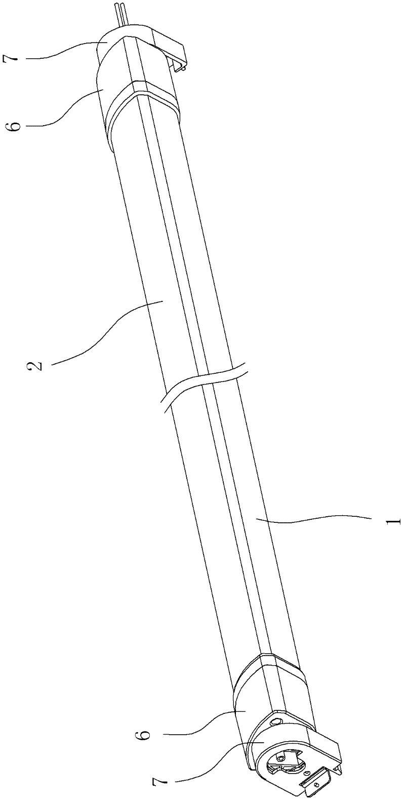
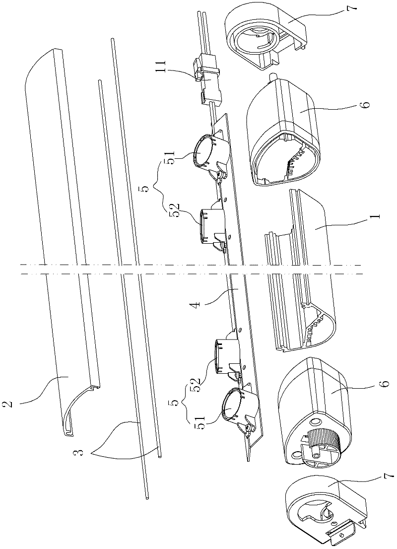
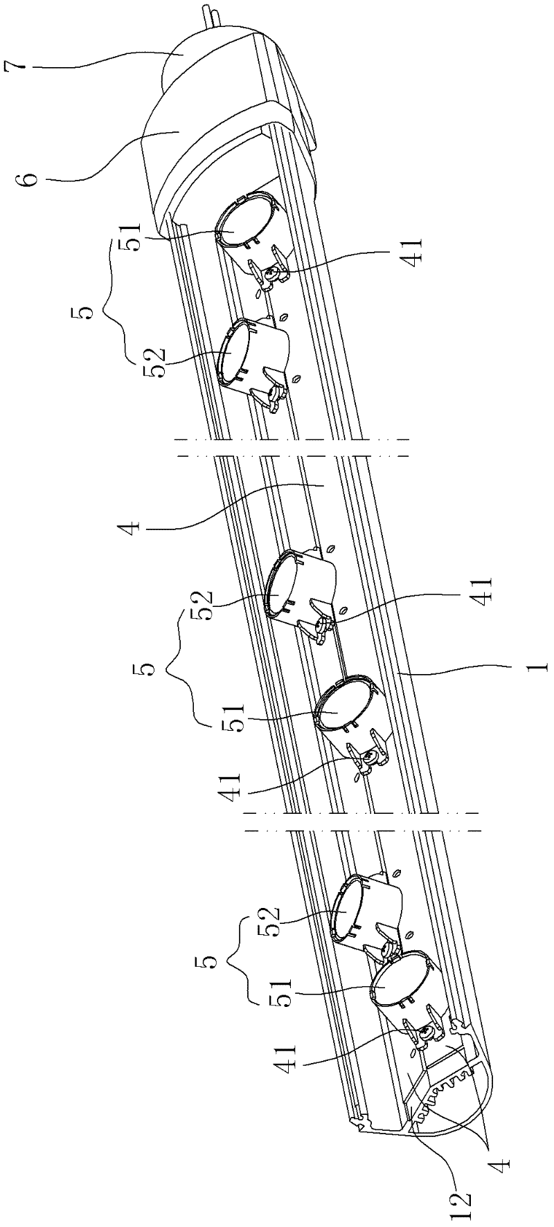
[0023] Such as Figure 1 ~ Figure 4 As shown, the illuminating lamps in this embodiment are set off from the centerline of the irradiation area, mainly to solve the problem of uneven illuminance when illuminating objects with such lamps set off from the centerline of the irradiation area, such as container lights.

[0024] The lighting lamp of this embodiment includes a lamp holder 1, the lampshade 2 is connected to the top of the lamp holder 1, and various connection structures in the prior art can be used between the lampshade 2 and the lamp holder 1, preferably using a slot structure to cooperate , in order to improve the connection tightness, the lampshade 2 and the lamp holder 1 are also provided with a sealing strip 3 at the joint; The socket 11 electrically connected with the circuit board 4, the socket 11 can be connected to an extern...


PUM


Abstract

The invention discloses an illumination lamp with uniform illuminance. The illumination lamp is deviated from a central line of an illumination area and comprises a lamp holder, a socket, and a light emitting module; the socket is arranged at the end of the lamp holder; the light emitting module is accommodated in the lamp holder and is electrically connected with the socket; and the illumination lamp is characterized in that the light emitting module comprises at least two groups of different light-emitting diode (LED) luminous bodies of which emergent light central lines are not consistent and illumination intensities are different. Multiple groups of the LED luminous bodies with different emergent light central line angles are arranged in the lamp holder, so that the illumination range is widened, the illuminance is improved, and the phenomenon that the illumination is not uniform when an object is irritated by LED luminous body groups with single emergent light central line angles is avoided; a lens is not needed to be arranged in single LED luminous body; the illumination lamp has a simple whole structure and is convenient to install; and the intersection angles of the emergent light central lines among different groups of LED luminous bodies can be adjusted or changed according to actual requirements, so that illumination of a required area can be obtained, and the illumination lamp can be adjusted flexibly and easily.

Description

technical field [0001] The invention relates to an illuminating lamp, in particular to an illuminating lamp with uniform illuminance. Background technique [0002] As a new type of lighting source, LED has the advantages of energy saving, environmental protection, high luminous efficiency and long service life, but due to the unequal distance between the light beam emitted by the LED light source and the illuminated object, uneven illumination and light divergence will occur. Problems, especially when the LED light source is set off from the center line of the irradiation area, for example, when the LED light source is set at a position flush with the top of the cabinet, the distance between the LED light source and the top of the cabinet is the closest, and the irradiation light is brighter. The distance from the light source to the bottom of the cabinet is the farthest, and the irradiated light is relatively dark, resulting in uneven illumination up and down the entire con...

Claims


Application Information

Patent Timeline
IPC IPC(8): F21S8/00F21V19/00F21V17/00F21Y101/02
CPCF21V21/00F21Y2111/004F21S4/008F21V15/02F21S8/00F21Y2103/003F21Y2101/02F21S4/28F21Y2103/10F21Y2107/20F21Y2115/10
Inventor 张发伟朱桃林郑兆勇林万炯
Owner 林万炯
Learn More