Imaging device and image restoration method

A camera device and image technology, applied in image communication, image enhancement, image data processing, etc., can solve problems such as inability to obtain high-resolution restored images

Active Publication Date: 2012-04-18
PANASONIC CORP
View PDF6 Cites 5 Cited by
  • Summary
  • Abstract
  • Description
  • Claims
  • Application Information

AI Technical Summary

Problems solved by technology

[0007] In addition, as shown in Patent Document 2, even when the restoration calculation of the degraded image is performed using the PSF image obtained by capturing the point light source instead of the PSF data created by the computer, especially when the PSF image is captured, the When the unnecessary luminance of the element (hereinafter also referred to as "noise") is large, there is a difference between the PSF shown in the PSF image and the actual PSF due to the influence of the noise
As a result, there is a problem that a high-resolution restored image cannot be obtained

Method used


Image

  • Imaging device and image restoration method
  • Imaging device and image restoration method
  • Imaging device and image restoration method

Examples


Embodiment 1

[0060] Hereinafter, Embodiment 1 of the present invention will be described with reference to the drawings.

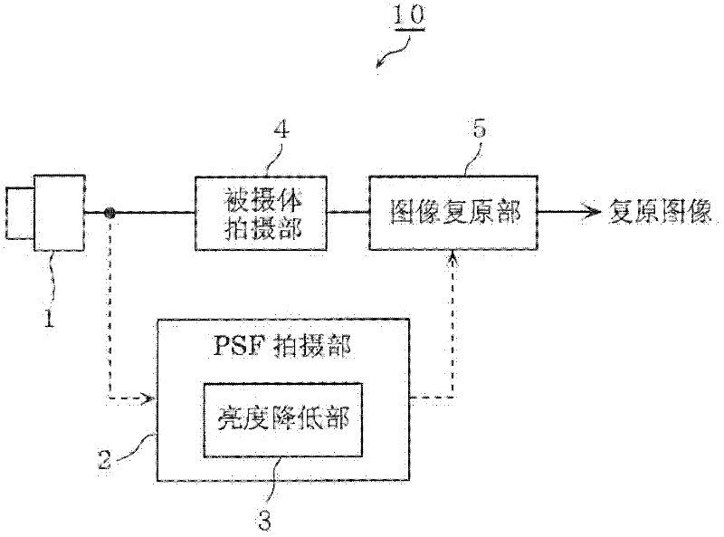
[0061] figure 1 It is a block diagram showing the configuration of the imaging device according to Embodiment 1 of the present invention. The imaging device 10 includes an optical system 1 , a PSF imaging unit 2 including a brightness reduction unit 3 , a subject imaging unit 4 , and an image restoration unit 5 .

[0062] The optical system 1 acquires a subject image. Specifically, the optical system 1 includes, for example, a lens, an imaging element, and the like. The optical system 1 generates a PSF image I_psf(x, y) by capturing a point image or an object image equivalent to a point image. Furthermore, the optical system 1 generates a subject image I_img(x, y) by capturing an arbitrary subject image.

[0063] The PSF imaging unit 2 captures a point image or an object image corresponding to the point image with the optical system 1 in order to obtain a PSF corre...

Embodiment 2

[0113] The configuration of the imaging device 10 according to the second embodiment of the present invention is the same as that of the first embodiment. figure 1 To represent. In this example, figure 1 The operation of the brightness reducing unit 3 in the block diagram is different from that of the first embodiment. Since other operations are the same as in Embodiment 1, description thereof is omitted.

[0114] The luminance reduction unit 3, when there is fixed-value noise that does not change in time series depending on the image position (for example, noise that occurs due to dark current noise or a manufacturing defect of an imaging element at a predetermined row or pixel position, etc.) , as shown in (Equation 2), the luminance value Nf(x, y) of the fixed value noise at each image position investigated in advance is subtracted from the PSF image I_psf(x, y).

[0115] Then, as shown in (Equation 4), the luminance reducing unit 3, for each image position of the PSF im...


PUM


Abstract

Disclosed is an imaging device that can restore degraded images to a high resolution when restoring degraded images on the basis of a point spread function (PSF) image that has been imaged by an optical system. The imaging device (10) has: an optical system (1); a PSF imaging unit (2) that acquires PSF information imaged by the optical system (1) and outputs corrected PSF information; a subject imaging unit (4) that acquires and outputs subject information imaged by the optical system (1); and an image restoration unit (5) that performs a restoration computation of the subject information on the basis of the corrected PSF information and the subject information. The PSF imaging unit (2) outputs corrected PSF information by subtracting, from the PSF information, correction brightness values that are greater by a brightness value (Is) than the brightness values (Nf) of fixed-value noise that does not vary chronologically.

Description

technical field [0001] The present invention relates to a technique for restoring an image degraded at the time of shooting to an image with little degradation. Background technique [0002] There is progress in the development of technologies for restoring images degraded by optical system misfocus, shake, or aberrations during shooting to images with less degradation. For example, in the technique disclosed in Patent Document 1, by performing a restoration operation using a correction function on a degraded image (captured image) degraded due to misfocus, blur, aberration, etc., a degeneration-corrected restoration can be obtained. For an image, this correction function has an inverse characteristic of a PSF (Point Spread Function: Point Spread Function) based on misfocus, blur, or aberration. In many cases, the correction function is created using PSF data created by a computer based on design data or the like. [0003] Furthermore, in the technique disclosed in Patent ...

Claims


Application Information

Patent Timeline
Patent Type & Authority Applications(China)
IPC IPC(8): H04N5/243G06T5/20H04N1/409H04N5/232
CPCG06T5/003H04N1/409
Inventor 大山一朗
Owner PANASONIC CORP
Why Eureka
Try Eureka