Uv liquid steriliser

A fluid and fluid treatment technology, applied in the field of disinfection of beverages and liquid food, can solve the problems of high cost, no commercial value, energy consumption, etc., and achieve high reliability, constant and fully mixed effect

Inactive Publication Date: 2012-04-25
STERIFLOW
View PDF9 Cites 7 Cited by
  • Summary
  • Abstract
  • Description
  • Claims
  • Application Information

AI Technical Summary

Benefits of technology

This patented technology allows for continuous or complete sterilization without any movement that could cause damage during use. It uses specialized equipment made up from multiple components - all part being immovable – which makes sure they work properly even if there's some leakage on them over time.

Problems solved by technology

Technologies described include current methods of treating foodstuffs containing harmful organism(Bailey et al.) These technics involve thermal pasteurizers, ultraviolet ray emitters, and other technical means like UVC lamp systems. However, they suffer from various drawbacks including complexity, low efficiency, lack of durable mechanism, difficulty handling large volumes of fluid, and environmental concerns associated therewith.

Method used


Image

  • Uv liquid steriliser
  • Uv liquid steriliser
  • Uv liquid steriliser

Examples


Embodiment Construction

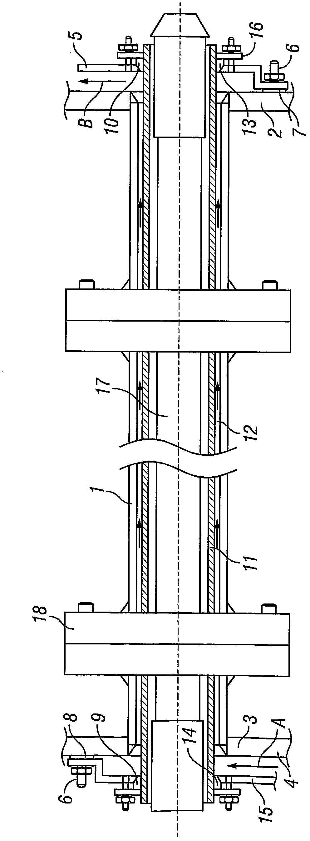
[0048] Refer to the attached figure 1 , in the first embodiment of the fluid disinfection device, the reaction chamber 1 is connected between the end plates 2&3. Preferably, the reaction chamber is welded to the end plates such that the weld is polished to provide a hygienic food grade seal.

[0049] An inlet manifold 4 and an outlet manifold 5 are located adjacent to the reaction chamber, said inlet manifold and said outlet manifold being connected to end plates 2 & 3 by fasteners 6 . The inlet manifold 4 and outlet manifold 5 are made watertight by seals 7 & 8 sandwiched between the inlet and outlet manifolds 4 & 5 and the end plates 2 & 3 .

[0050] A tubular sleeve 11 is longitudinally centered and concentrically positioned within the reaction chamber 1 such that it protrudes through the end plates 2 & 3 and through holes 9 & 10 in the inlet and outlet manifolds 4 & 5 .

[0051] Preferably, the tubular sleeve is a good transmitter of germicidal wavelengths (220nm-280nm)....


PUM


Abstract

A fluid treatment apparatus particularly for sterilising drinks comprises an elongate tubular duct (110) and an elongate UV light source (111) extending longitudinally of the duct (110). The fluid flows longitudinally of the duct (110) in a thin annular low passage (114) which extends around the UV light source (111). A mixing device (112) disposed between adjacent longitudinal portions of the duct (110) for diverts all of the fluid flowing along a first portion of the passage (114) through fluid mixing means (113,116) in the device (112) and returns the mixed fluid to a second portion of the passage (114). Micro-organisms in the thin flow of fluid are killed as they come within close proximity of the light source (111). The mixing device (112) causes all of the flow to be thoroughly mixed and returned to the flow passage (114). The provision of a plurality of mixing devices along the length of the duct (110) increases the likelihood that all microorganisms receive a sufficient lethal dose of UV radiation.

Description


Claims


Application Information

Patent Timeline
Owner STERIFLOW
Why Eureka
Try Eureka