
Double-end pressure riveting method, riveting pin and pressure riveting device

A riveting pin and double-ended technology, applied in rivets and other directions, can solve problems such as journal upsetting, component product performance degradation, and functional failure, and achieve the effects of stable riveting process, reduced riveting cost, and improved quality

Active Publication Date: 2012-05-02
SUZHOU DONGFENG FINEBLANKING ENG
View PDF9 Cites 11 Cited by
  • Summary
  • Abstract
  • Description
  • Claims
  • Application Information

AI Technical Summary

Problems solved by technology

First of all, due to the limitation of the structure and working principle of the spin riveting machine, it can only be riveted at one end when riveting. , multi-step riveting is required, the efficiency is too low
Secondly, when the space of the riveted parts is very tight, the riveting process is unstable due to the rotation of the riveting head and the surrounding parts are easily scratched, and the appearance of the riveted parts is defective; and when the riveting head is worn, burrs will be generated during the riveting process, and there will be scratches finger safety hazard
Furthermore, when the rivet pin (nail) is solid and the diameters at both ends are large, the force required for the riveting will be very large, which will easily cause the journal of the middle section of the rivet pin (nail) to be upset, and the parts to be riveted with the rivet pin (Nail) The parts with clearance fit in the middle section of the journal are riveted, resulting in product performance degradation or functional failure.

Method used


Image

  • Double-end pressure riveting method, riveting pin and pressure riveting device
  • Double-end pressure riveting method, riveting pin and pressure riveting device
  • Double-end pressure riveting method, riveting pin and pressure riveting device

Examples


Embodiment Construction

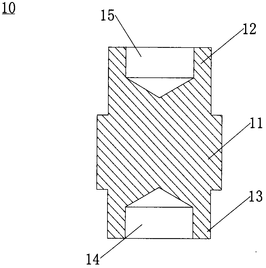
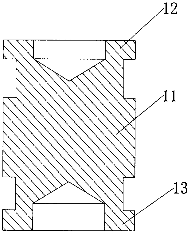
[0024] like figure 1 and figure 2 As shown, the riveting pin used in the double-end pressure riveting method is a three-segment journal riveting pin 10, the size of the middle journal 11 is larger than that of the two ends of the journals 12 and 13, and the two ends of the journal are partially hollow Structure; after pressure riveting, the journals at both ends of the riveting pin are locally upset. Since the journals at both ends are provided with recesses 15 and 14 along the axial direction of the riveting pin, the outer walls of the recesses are locally upset after riveting.

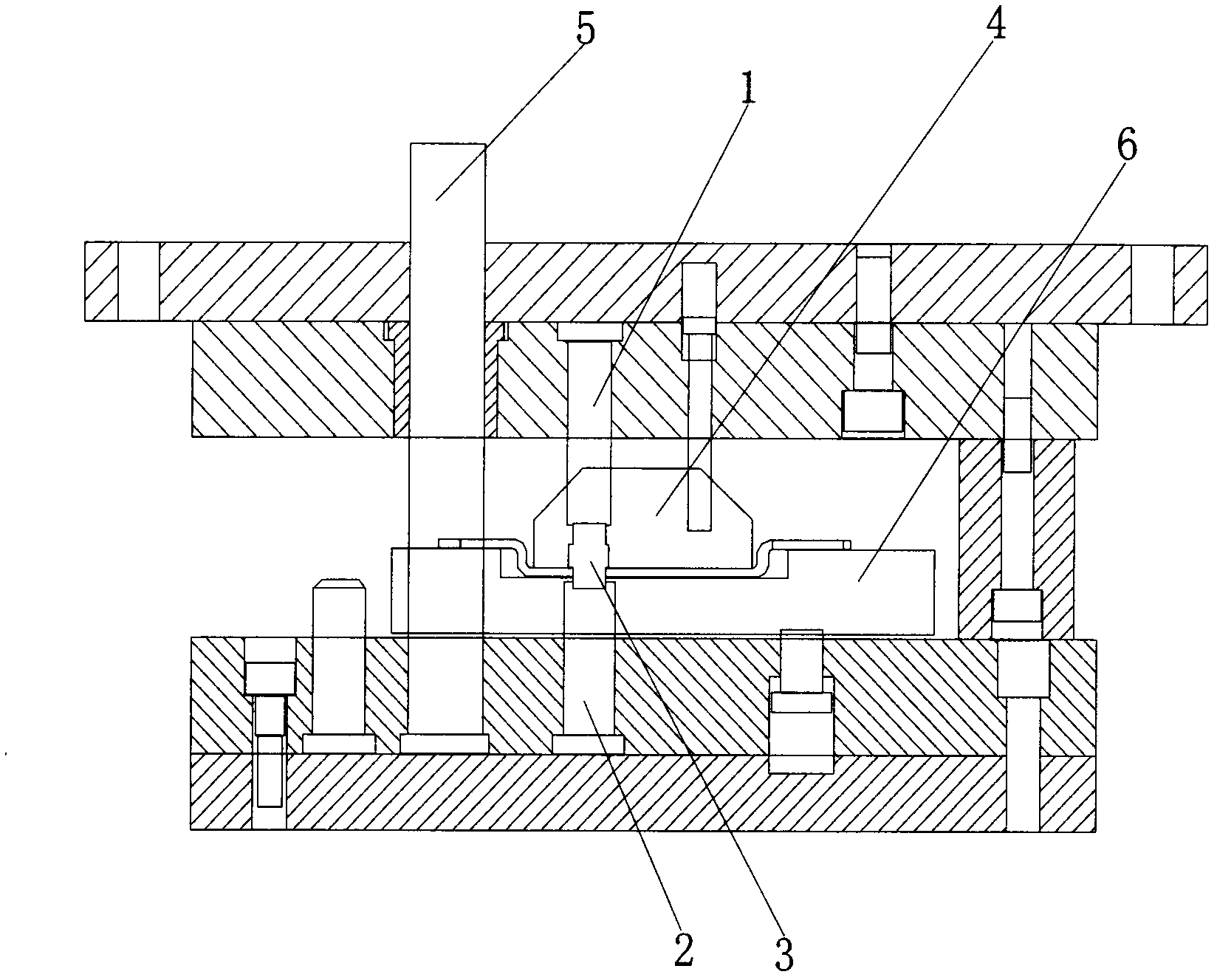
[0025] like image 3 As shown, the riveting device used in the double-ended riveting method includes an upper riveting die and a lower riveting die, the upper riveting head 1 and the lower riveting head 2 are respectively fixed on the upper riveting die and the lower riveting die, and the upper riveting die and the lower riveting die are fixed respectively. A riveting guide post 5 is arranged bet...


PUM


Abstract

Disclosed are a double-end pressure riveting method, a riveting pin and a pressure riveting device. The pressure riveting method includes that a part to be riveted is fixed by a clamping fixture, an upper riveting head and a lower riveting head are fixed onto a pressure riveting die, the riveting pin is placed, and then the riveting heads linearly move to squeeze two ends of the riveting pin and perform pressure riveting for the double ends simultaneously. The riveting pin is a three-journal type riveting pin, the size of a middle journal of the riveting pin is larger than that of each of journals at the two ends of the riveting pin, the journals at the two ends are in partially hollow structures, and the journals at the two ends of the riveting pin after pressure riveting are partially upset. The double-end pressure riveting method can be used for realizing double-end pressure riveting for a plurality of riveting pins simultaneously, the riveting process is stable and reliable, riveting efficiency and quality are improved obviously, and riveting cost is reduced.

Description

technical field [0001] The invention belongs to the riveting connection technology of metal parts, and in particular relates to a double-end riveting method for realizing a double-end riveting process, a riveting pin and a riveting device. Background technique [0002] Riveting refers to the method of using axial force to thicken the head of the riveting pin (nail) to connect and fix multiple parts; from the principle of riveting, it can be divided into spin riveting and pressure riveting. At present, the traditional riveting process is mostly single-end spin riveting, but due to the limitation of the process itself, it has the following problems. First of all, due to the limitation of the structure and working principle of the spin riveting machine, it can only be riveted at one end when riveting. , it needs to be riveted in multiple steps, and the efficiency is too low. Secondly, when the space of the riveted parts is very tight, the riveting process is unstable due to t...

Claims


Application Information

Patent Timeline
IPC IPC(8): B21J15/10F16B19/08
Inventor 韩传飞
Owner SUZHOU DONGFENG FINEBLANKING ENG
Learn More