Fluid-filled type vibration damping device

A vibration isolation and fluid technology, which is applied in the direction of power plants, jet propulsion devices, internal combustion propulsion devices, etc., can solve problems such as difficult safety valve deformation, spring characteristics, reduction of fluid flow, and easy cracking, etc., to achieve improved quietness, The effect of preventing abnormal sound and preventing the generation of abnormal sound

Active Publication Date: 2012-05-02
SUMITOMO RIKO CO LTD
View PDF3 Cites 13 Cited by
  • Summary
  • Abstract
  • Description
  • Claims
  • Application Information

AI Technical Summary

Problems solved by technology

[0005] However, in the structure described in Patent Document 1, the entirety of the safety valve is in the shape of a thin film with a constant thickness, so that when a negative pressure is generated in the pressure receiving chamber, the entirety of the safety valve tends to be greatly deformed so that the leak path becomes connected state
Therefore, when the vibration is input, the pressure fluctuation of the pressure receiving chamber is lost through the leakage passage, and even if the safety valve is kept in the cut-off state, the pressure fluctuation of the pressure receiving chamber is lost to the balance chamber side due to the elastic deformation of the safety valve itself, thereby reducing The amount of fluid flow through the damping passage may be adversely affected, which may adversely affect the vibration isolation effect exerted by the damping passage
[0006] In addition, although it is also considered to increase the thickness of the safety valve to enhance the characteristics of the deformation spring, it is very difficult to make the deformation spring of the safety valve very difficult due to the restraint effect due to the integrally formed thick-walled parts on both sides of the safety valve in the circumferential direction. Adjust the characteristic to the appropriate value
Furthermore, since the film-shaped safety valve is protrudingly formed from the outer peripheral end surface of the thickest fixed portion formed on the outer peripheral edge portion of the movable membrane, there are also occurrences of stress concentration due to significant stress concentration toward the base end portion of the safety valve. Cracks and damage are likely to occur, and it is difficult to ensure durability and reliability

Method used


Image

  • Fluid-filled type vibration damping device
  • Fluid-filled type vibration damping device
  • Fluid-filled type vibration damping device

Examples


Embodiment Construction

[0035] Hereinafter, embodiments of the present invention will be described with reference to the drawings.

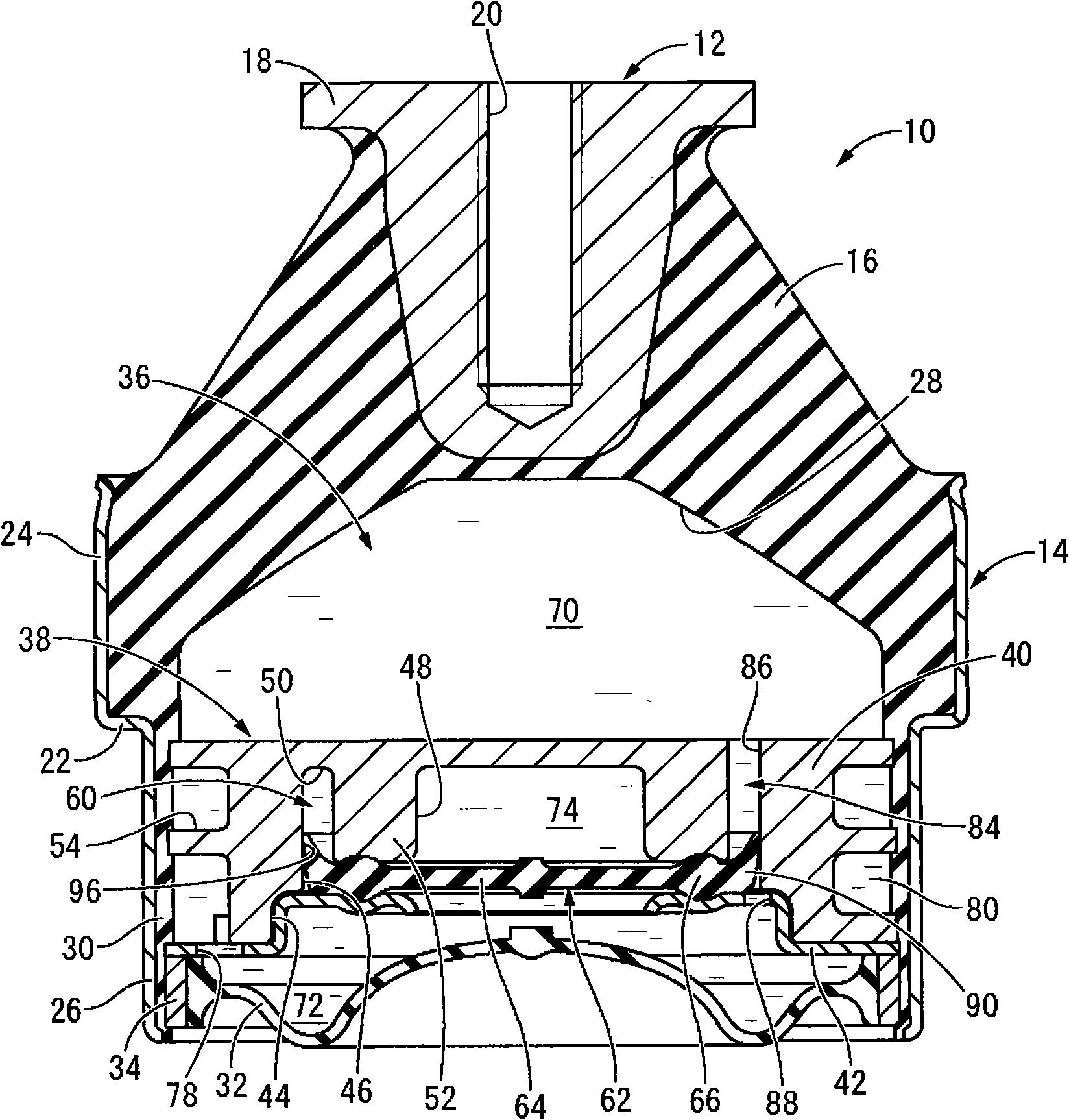
[0036] exist figure 1 In the figure, the engine mount 10 for automobiles which is one embodiment of the fluid-filled vibration isolation device of the structure which pertains to this invention is shown. The engine mount 10 has a structure in which a first mounting member 12 and a second mounting member 14 are connected by a main body rubber elastic body 16 . In addition, the first mounting member 12 is mounted on an unillustrated power unit, and the second mounting member 14 is mounted on an unillustrated vehicle body, whereby the power unit is vibration-isolated and supported by the vehicle body. In addition, in the following description, in principle, the up-down direction means figure 1 in the up and down direction.

[0037] In more detail, the first mounting member 12 has a solid substantially circular block shape, and a flange portion 18 protruding in a direc...


PUM


Abstract

A fluid-filled type vibration damping device including a partition member having a moveable film and a short passage interconnecting a pressure receiving chamber and an equilibrium chamber. A valve member that switches between a communicating state and a shut off state of the short passage projects from the moveable film. The valve member has a thick walled part and a thin walled part, the thin walled part being pressed on an inner wall surface of the short passage. A pressure of the pressure receiving chamber is applied through the short passage to a pressure receiving chamber side surface of the thick walled part, while an equilibrium chamber side surface thereof is supported by the partition member. The pressure of the pressure receiving chamber is applied to one side of the thin walled part and a pressure of the equilibrium chamber is applied to another side thereof through the short passage.

Description

technical field [0001] The present invention relates to a vibration isolator suitable for, for example, an engine mount of an automobile, and more particularly, to a fluid-enclosed type vibration isolator utilizing the flow action of a fluid enclosed inside. Background technique [0002] Conventionally, a fluid-filled type vibration isolator is known as one type of vibration isolator applied to an engine mount, a subframe mount, and the like of an automobile. In the fluid-enclosed vibration isolation device, the first mounting member and the second mounting member are connected by a main body rubber elastic body, and a pressure receiving chamber and a balancing chamber filled with incompressible fluid are formed, and the fluid passes through the The orifice passage through which the above-mentioned pressure receiving chamber and the balance chamber communicate with each other flows, thereby exerting the intended vibration isolation effect. [0003] However, in the fluid-fil...

Claims


Application Information

Patent Timeline
Patent Type & Authority Applications(China)
IPC IPC(8): B60K5/12F16F13/10
Inventor 石川亮太小川雄一清水赖重
Owner SUMITOMO RIKO CO LTD
Why Eureka
Try Eureka