Method and apparatus for dispense of chemical vapor in a track lithography tool

a technology of chemical vapor and lithography tool, which is applied in the direction of chemical vapor deposition coating, coating, metallic material coating process, etc., can solve the problems of many defects, limited flexibility and delivery rate, difficult control, etc., and achieve the effect of eliminating negative pressur

Inactive Publication Date: 2008-03-20
SOKUDO CO LTD
View PDF5 Cites 5 Cited by
  • Summary
  • Abstract
  • Description
  • Claims
  • Application Information

AI Technical Summary

Benefits of technology

[0009] Systems and methods in accordance with embodiments of the present invention provide for dispensing a flow of photolithography chemical vapor into a chamber. A buffer vessel and a vapor tube in a track tool are configured as a diffusion vaporizer to deliver a flow of photolithography chemical vapor to the chamber for coating a wafer. Pressure in the buffer vessel is equalized to eliminate negative pressure in the buffer vessel. The size of the buffer vessel is selected such that a volume of photolithography chemical vapor that is sufficient to coat an entire lot of wafers is provided to the chamber when there is no longer any photolithography chemical in a source bottle.

Problems solved by technology

This delivery method requires a large volume of photolithography chemical to be heated, is difficult to control, has limited flexibility and delivery rate, and is prone to many defects due to liquid particles.
Present systems do not provide the level of control desirable for current and future track lithography HMDS vapor delivery tools.

Method used


Image

  • Method and apparatus for dispense of chemical vapor in a track lithography tool
  • Method and apparatus for dispense of chemical vapor in a track lithography tool
  • Method and apparatus for dispense of chemical vapor in a track lithography tool

Examples


Embodiment Construction

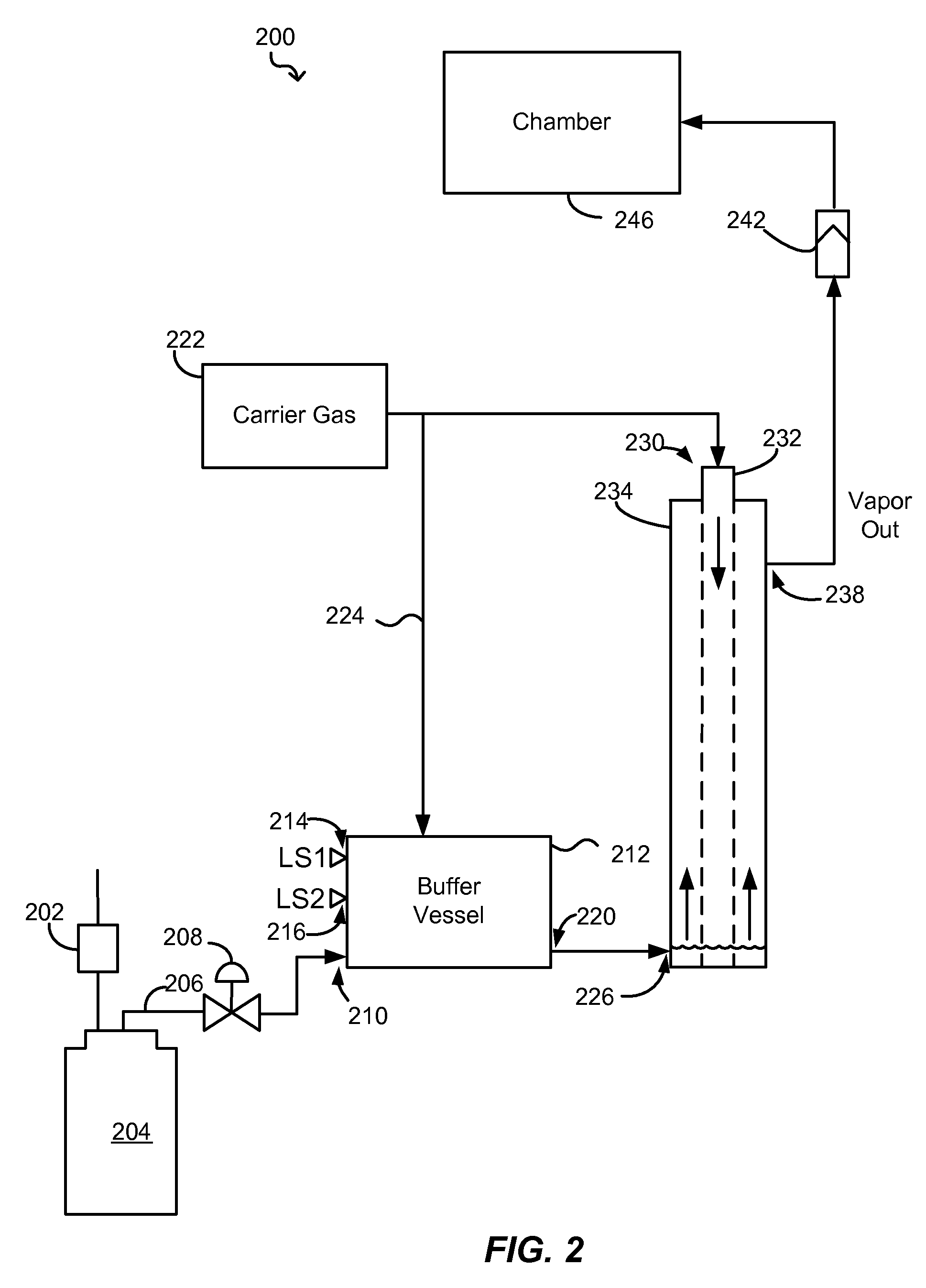
[0019] Systems and methods in accordance with various embodiments of the present invention overcome the afore-mentioned and other deficiencies in existing dispense systems by providing a buffer vessel and a vapor tube that are configured to behave as a diffusion vaporizer to deliver photolithography chemical vapor in a track tool. Pressure in the buffer vessel is equalized to prevent negative pressure in the buffer vessel. The size of the buffer vessel is selected such that a volume of the photolithography chemical vapor provided to a chamber is sufficient to coat an entire lot of wafers when there is no longer any photolithography chemical in a source bottle.

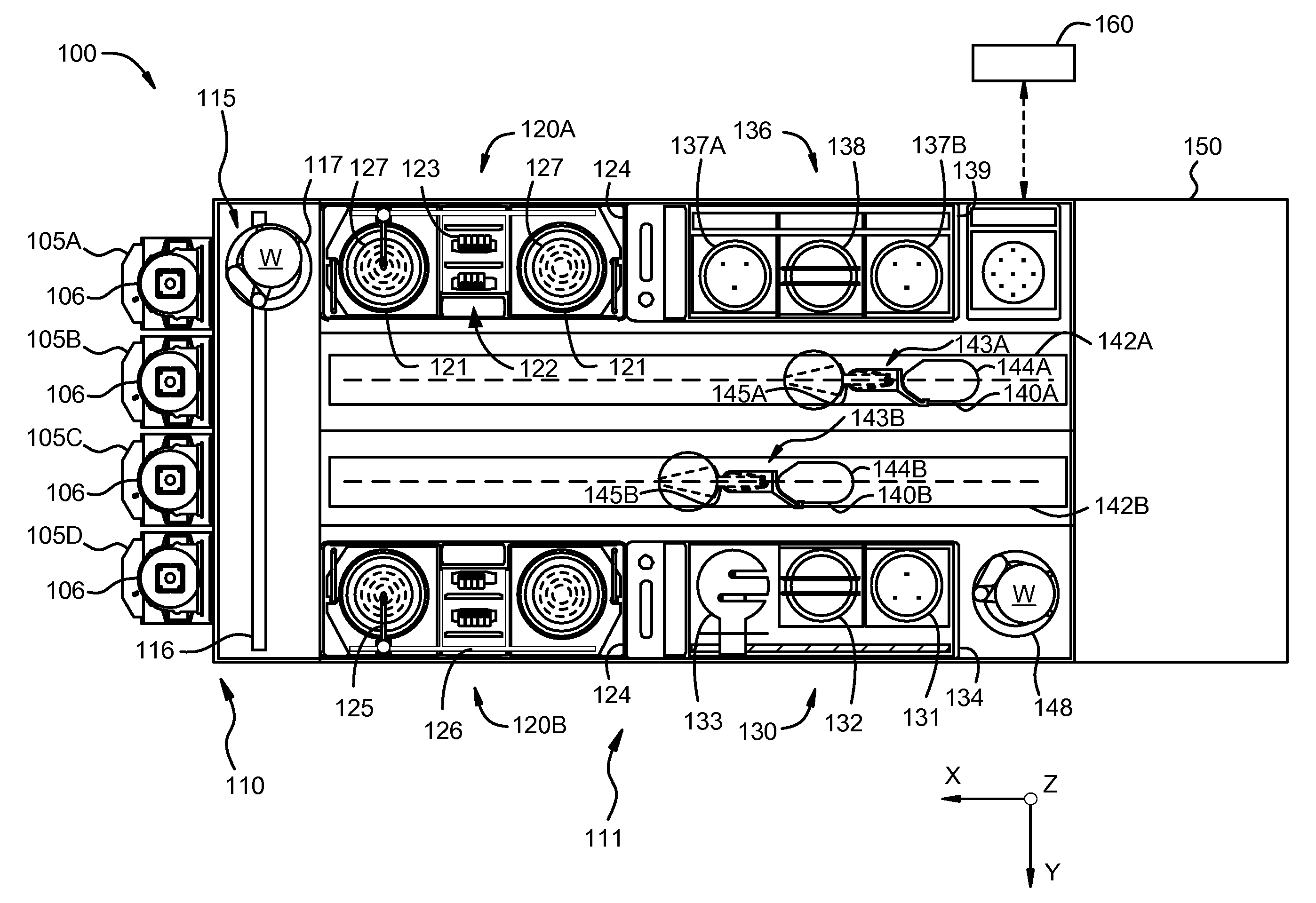
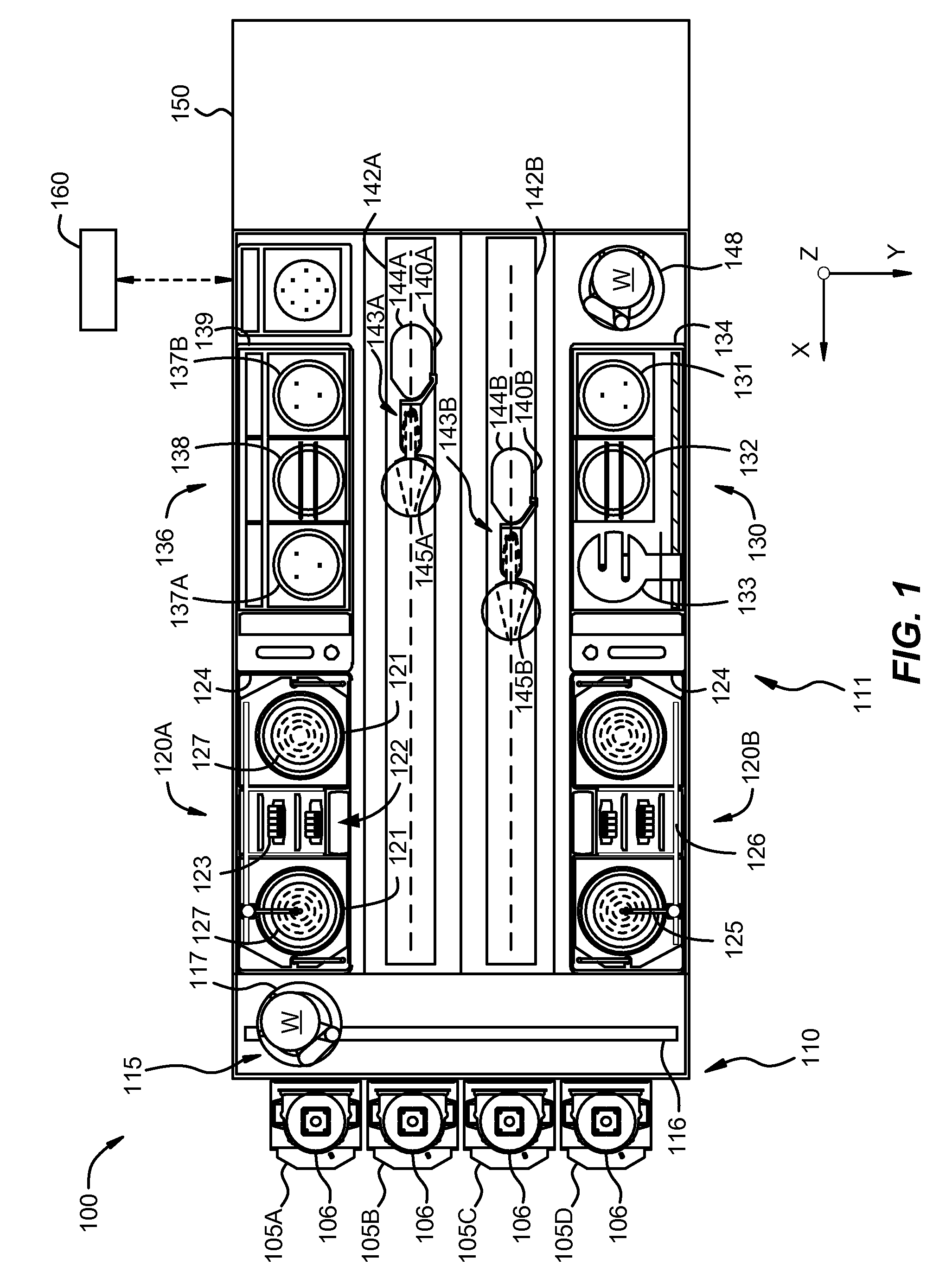
[0020]FIG. 1 is a plan view of an embodiment of a track lithography tool 100 in which the embodiments of the present invention may be used. As illustrated in FIG. 1, track lithography tool 100 contains a front end module 110 (sometimes referred to as a factory interface or FI) and a process module 111. In other embodiments, th...


PUM

PropertyMeasurementUnit
pressureaaaaaaaaaa
volumeaaaaaaaaaa
sizeaaaaaaaaaa

Abstract

A buffer vessel and a vapor tube in a track tool are configured as a diffusion vaporizer to deliver a flow of photolithography chemical vapor to a chamber for coating a wafer. Pressure in the buffer vessel is equalized to eliminate negative pressure in the buffer vessel. The size of the buffer vessel is selected such that a volume of photolithography chemical vapor that is sufficient to coat an entire lot of wafers is provided to the chamber when there is no longer any photolithography chemical in a source bottle.

Description

CROSS-REFERENCES TO RELATED APPLICATIONS [0001] The present application claims benefit under 35 U.S.C. § 119(e) of U.S. Provisional Patent Application No. 60 / 821,918, filed Aug. 9, 2006, entitled “Photolithography Chemical Vapor Dispense System for a Track Tool,” which is incorporated herein by reference in its entirety.BACKGROUND OF THE INVENTION [0002] The present invention relates generally to the field of substrate processing equipment. More particularly, the present invention relates to the delivery of photolithography chemical vapor in a track tool. Merely by way of example, the method and apparatus of the present invention are used to deliver photolithography chemical vapor in a track tool using a diffusion vaporizer. The method and apparatus can be applied to other processes for semiconductor substrates, for example those used in the formation of integrated circuits. [0003] Modern integrated circuits contain millions of individual elements that are formed by patterning the m...

Claims


Application Information

Patent Timeline
Patent Type & Authority Applications(United States)
IPC IPC(8): C23C16/00
CPCH01L21/67225
Inventor LIN, Y. SEAN
Owner SOKUDO CO LTD
Why Eureka
Try Eureka