Mail feeding device

a feeding device and a technology for mail items, applied in audible signalling systems, lighting and heating apparatuses, instruments, etc., can solve the problems of inability to realize high-speed feeding of mail items, inability to quickly eliminate negative pressure applied to mail items, etc., and achieve the effect of positive elimination of negative pressur

Inactive Publication Date: 2011-06-07
KK TOSHIBA
View PDF5 Cites 4 Cited by
  • Summary
  • Abstract
  • Description
  • Claims
  • Application Information

AI Technical Summary

Benefits of technology

[0010]In the above-described invention, since air is introduced into the negative-pressure chamber to positively eliminate negative pressure therein after a mail item picked up from the pickup position, held on the pickup member by the negative pressure of the negative-pressure chamber and picked up from the pickup position, is transferred to the conveyance section, subsequent mail items, which have been picked up unintentionally simultaneously with the first-mentioned mail item, are prevented from being rendered to the negative pressure of the negative-pressure chamber, whereby accumulated mail items can be quickly picked up one by one at desired timing.

Problems solved by technology

However, in the above structure, even if the solenoid valve is closed to stop suction by the suction nozzle, negative pressure applied to a mail item cannot quickly be eliminated where the mail item is held by the belt by a suction force.
Accordingly, even if the on / off cycle of the solenoid valve is shortened to feed mail items at high speed, high-speed feeding of mail items cannot be realized since negative pressure applied to the mail items cannot quickly be eliminated.

Method used


Image

  • Mail feeding device
  • Mail feeding device
  • Mail feeding device

Examples


first embodiment

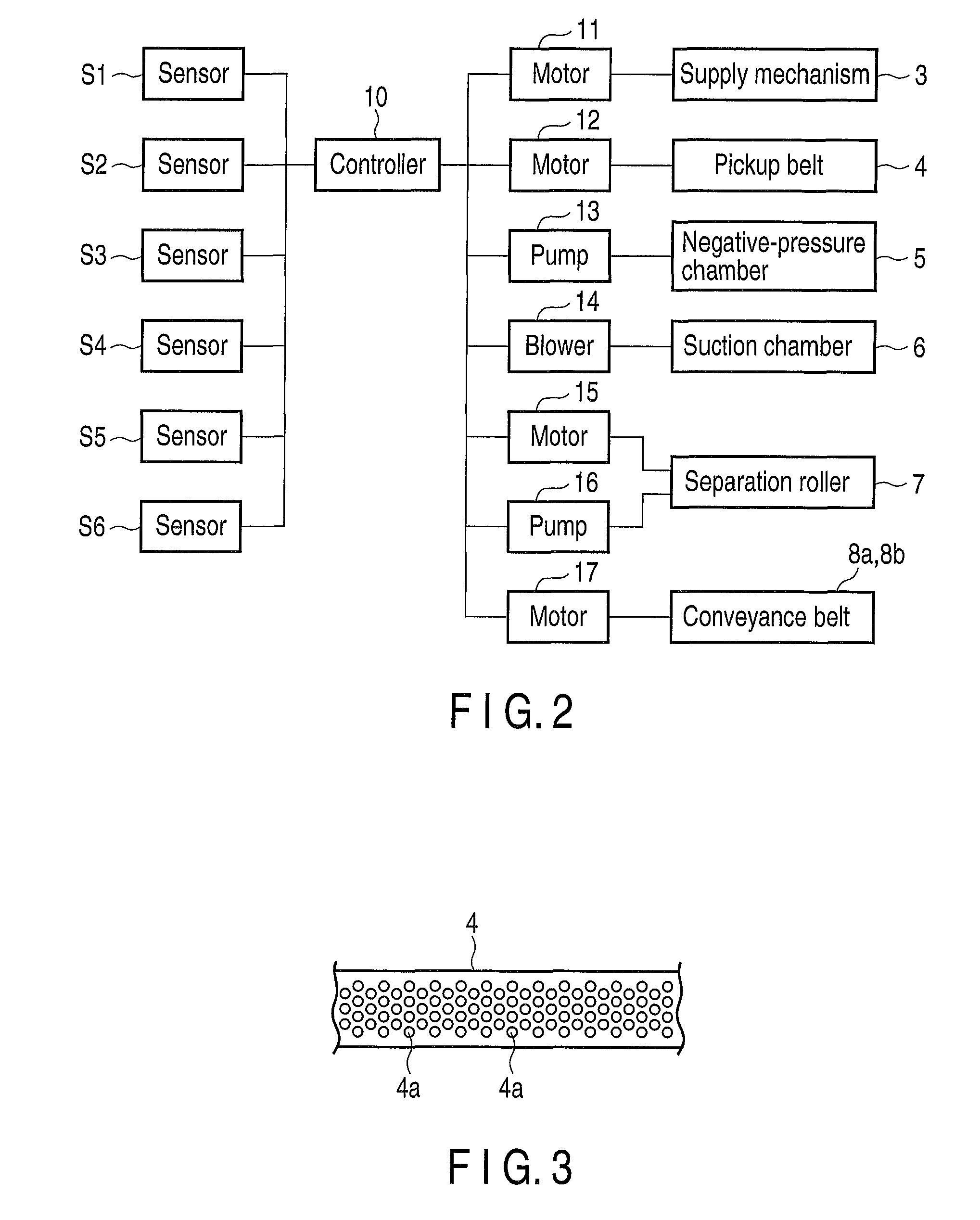
[0048]FIG. 4 schematically shows the essential structure of the feeding device 1 with a pressure adjustment unit 20 according to the invention. The pressure adjustment unit 20 comprises a suction pipe 22 for feeding air into the negative-pressure chamber 5, and an electromagnetic valve 24 (on / off valve) provided across the suction pipe 22. The electromagnetic valve 24 is on / off controlled by the controller 10.

[0049]Thus, in the first embodiment, the pump 13 is always operated to keep, at a negative value, the internal pressure of the negative-pressure chamber 5, and the electromagnetic valve 24 is opened when no mail item P should be stuck to the pickup belt 4 by negative pressure. The suction pipe 22 has a large diameter so that when the electromagnetic valve 24 is opened, the amount of air flowing via the suction pipe 22 into the negative-pressure chamber 5, which has its internal pressure kept at a negative value by the pump 13, is much greater than the amount of air drawn by the...

second embodiment

[0059]FIG. 7 is a graph illustrating the relationship between variations in the internal pressure of the negative-pressure chamber 5 and the on / off timing of the electromagnetic valve 34 of the pressure adjustment unit 30. From this graph, it is evident that immediately after the electromagnetic valve 34 is opened, the internal pressure of the negative-pressure chamber 5 is more quickly increased to the atmospheric pressure than in the case shown in FIG. 5. Namely, in the second embodiment, the exhaust air of the pump 13 abruptly flows into the negative-pressure chamber 5 upon the opening of the electromagnetic valve 34, with the result that the pressure in the negative-pressure chamber 5 is instantly increased to the atmospheric pressure.

[0060]FIG. 8 shows the essential part of a feeding device 1 with a pressure adjustment unit 30′ according to a modification of the above-described second embodiment. In this modification, an electromagnetic valve 38 is additionally provided across ...

third embodiment

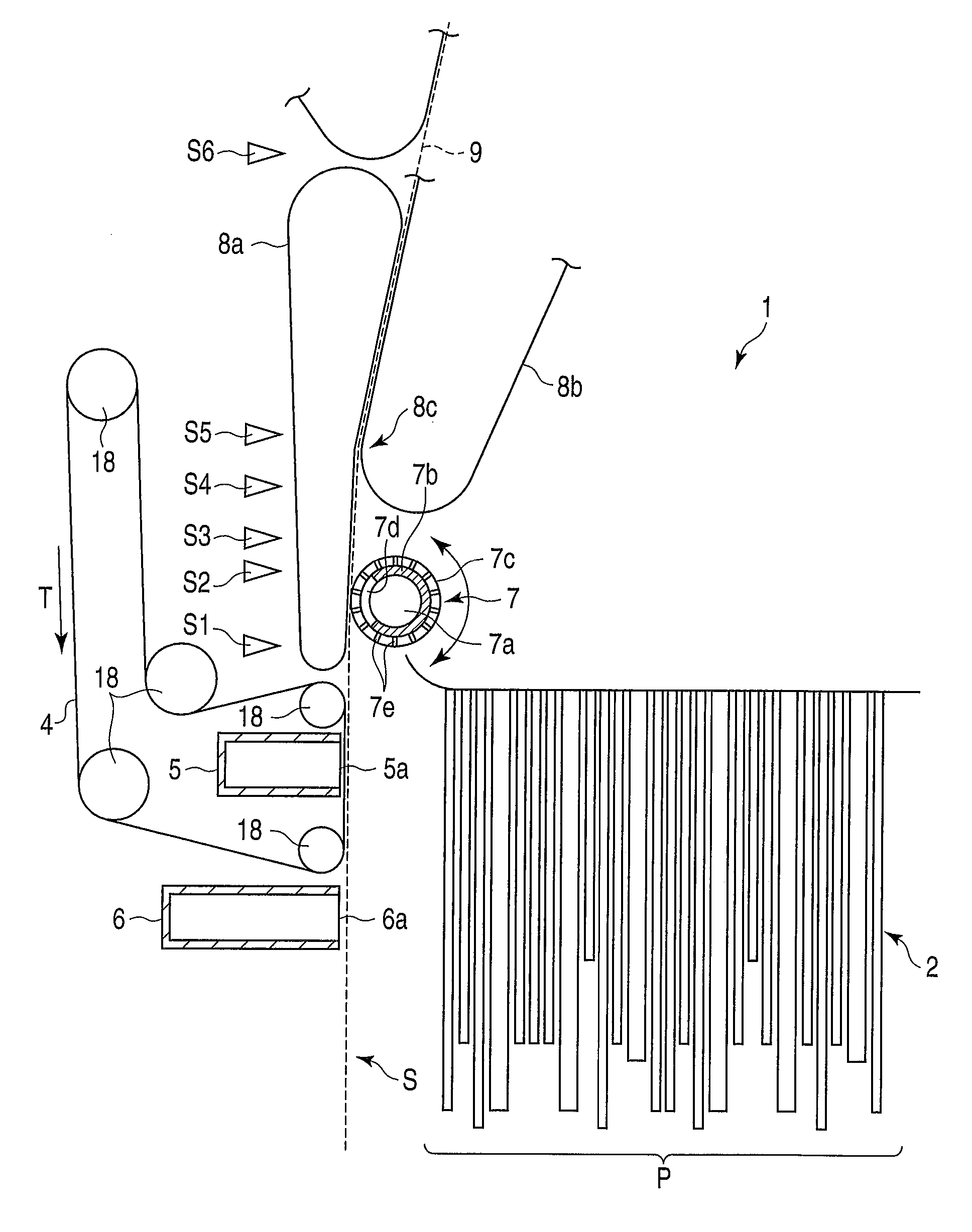
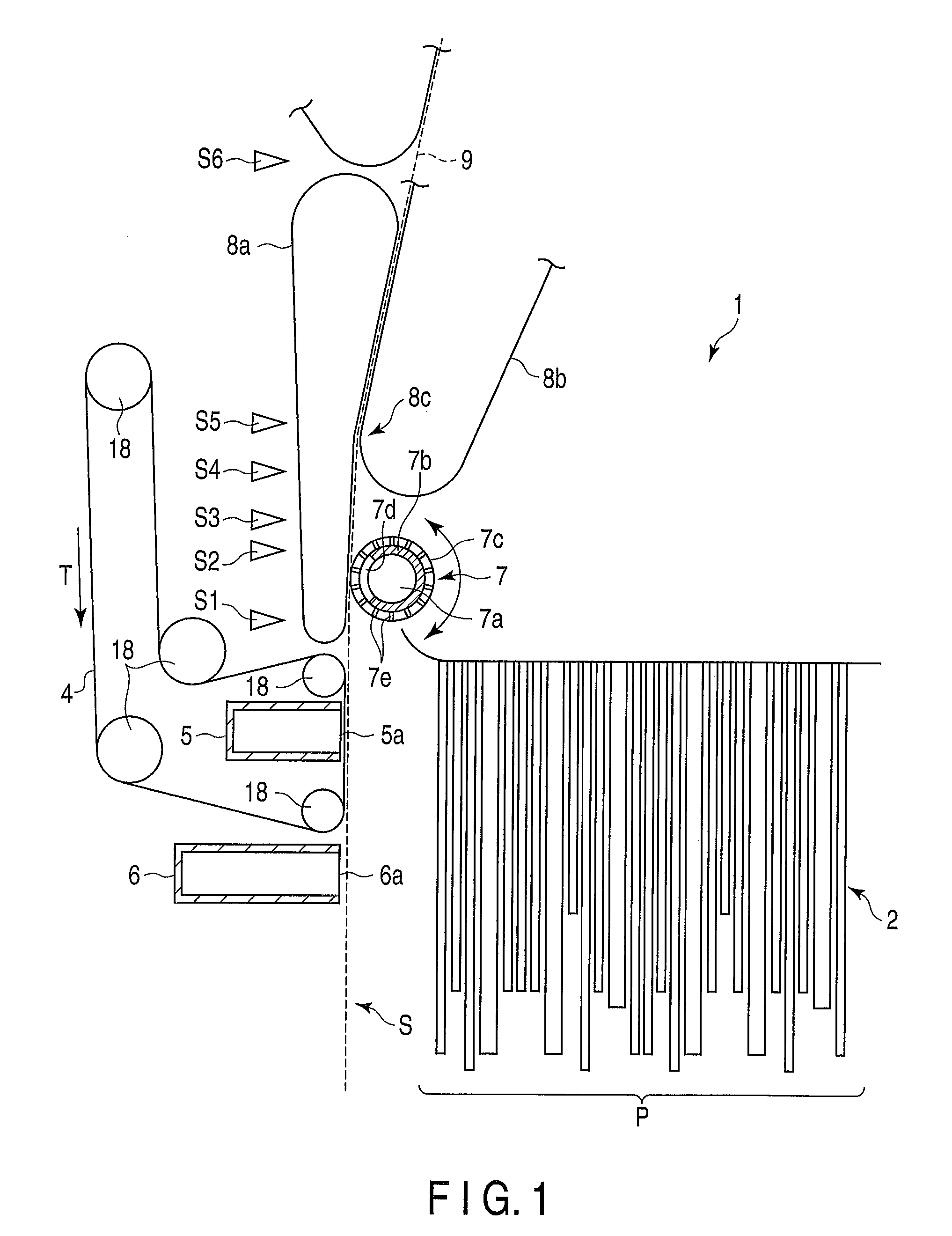
[0066]In particular, in the third embodiment, the exhaust air of the pump 16, which is used to draw air from the chamber 7a of the core 7b, is also used to return the internal pressure of the negative-pressure chamber 5 to the atmospheric pressure. However, the invention is not limited to this. For instance, the exhaust air of the blower 14, which is used to draw air from the suction chamber 6, may also be used to return the internal pressure of the negative-pressure chamber 5 to the atmospheric pressure. Alternatively, a dedicated air supply unit may be connected to the negative-pressure chamber 5.

[0067]When feeding a mail item P, the controller 10 of the feeding device 1 closes an electromagnetic valve 44 (on / off valve) provided across the exhaust pipe 42 of the pump 16, and causes the pump 13 to draw air from the negative-pressure chamber 5. At this time, the pump 16 for generating negative pressure around the separation roller 7 is made to continue its air drawing, and the thus-...


PUM


Abstract

A feeding device for feeding each of accumulated mail items P onto a conveyance path includes a pickup belt which runs along a pickup position, and a negative-pressure chamber opposing the pickup position with the pickup belt interposed therebetween. When each mail item is picked up from the pickup position and reaches a nip between conveyance belts, air is introduced into the negative-pressure chamber to eliminate negative pressure therein.

Description

CROSS-REFERENCE TO RELATED APPLICATIONS[0001]This application is based upon and claims the benefit of priority from prior Japanese Patent Application No. 2008-153037, filed Jun. 11, 2008, the entire contents of which are incorporated herein by reference.BACKGROUND OF THE INVENTION[0002]1. Field of the Invention[0003]The present invention relates to a mail feeding device for feeding a plurality of accumulated mail items one by one.[0004]2. Description of the Related Art[0005]A mail feeding device is known in which a belt with holes is run along mail items to hold them one by one, using a suction nozzle provided at the reverse side of the belt, thereby sequentially picking up them (see, for example, U.S. Pat. No. 5,391,051). In this device, a solenoid valve for executing on / off control of negative pressure is provided between a vacuum tank and the suction nozzle.[0006]In this structure, to pick up each mail item, the belt is run, the solenoid valve is opened, and the suction nozzle is...

Claims


Application Information

Patent Timeline
Patent Type & Authority Patents(United States)
IPC IPC(8): B65H5/08
CPCB65H3/124B65H7/02B65H7/16B65H2515/342B65H2801/66B65H2701/1311B65H2511/514B65H2220/02B65H2220/01B65H2515/34F21S13/10G08B5/36G08B3/00Y02B20/72
Inventor MITSUYA, YUSUKENARUOKA, YOSHIHIKO
Owner KK TOSHIBA
Why Eureka
Try Eureka