Clamping structure for fan column pipe

A column and fan technology, which is applied in the field of improvement and innovation technology, can solve the problems of time-consuming, labor-intensive and inoperable operation, and achieve the effect of simple structure realization and few parts and components.

Inactive Publication Date: 2012-05-02
MIDEA GRP CO LTD
View PDF5 Cites 3 Cited by
  • Summary
  • Abstract
  • Description
  • Claims
  • Application Information

AI Technical Summary

Problems solved by technology

[0002] Most of the existing column tube clamping mechanisms for fans use tools to lock the screws to clamp the column tube. The disadvantage of this structure is that tools must be used to install and disassemble, and it cannot be operated without tools. Problems such as time-consuming and labor-intensive operation

Method used


Image

  • Clamping structure for fan column pipe
  • Clamping structure for fan column pipe
  • Clamping structure for fan column pipe

Examples


Embodiment Construction

[0014] The present invention will be further described in detail below in conjunction with the accompanying drawings and embodiments.

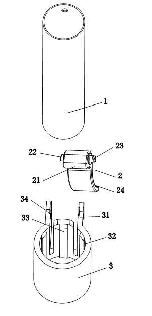
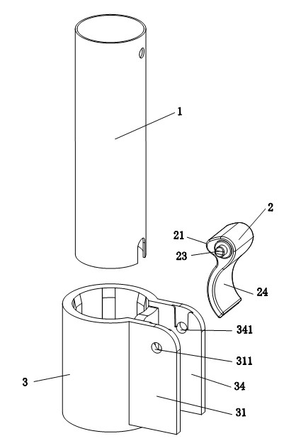
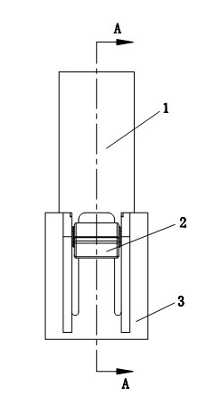
[0015] like Figures 1 to 6 As shown, a clamping and fixing mechanism for a fan column tube includes a column tube 1 and a body 3, one end of the column tube 1 can be directly inserted into the column tube hole 32 on the body 3, and the present invention is characterized in that it also includes a pressure rod 2; wherein the body 3 is provided with a first mounting arm 31 and a second mounting arm 34, and an elastic tongue structure 33 is provided on the wall of the body 3, and the elastic tongue structure 33 is located on the first mounting arm 31 and the second mounting arm 34; Between the mounting arms 34; the pressure rod 2 is installed between the first mounting arm 31 and the second mounting arm 34, the pressure rod 2 is a lever structure, and the long end of the pressure rod 2 is an exposed and operable movable buckle 24. The short end...


PUM


Abstract

The invention relates to a clamping structure for a fan column pipe, which comprises a column pipe and a body; one end of the column pipe can be directly inserted in a column pipe hole on the body. The clamping structure for column pipe of fan is characterized in that the clamping structure further comprises a pressing rod; the body is provided with a first installing arm and a second installing arm; an elastic tongue structure is arranged on the wall of the body; the elastic tongue structure is located between the first installing arm and the second installing arm; the pressing rod is installed between the first installing arm and the second installing arm; the pressing rod is in lever structure; the long end of the pressing rod is exposed and provided with an operable movable buckle; the short end of the pressing rod is provided with a gibbosity for tightening; two sides of the short end of the pressing rod are connected with the first installing arm and the second installing arm ina turning manner; and the gibbosity can be matched with the elastic tongue structure with the turning process of the pressing rod and can radically and inwardly press the elastic tongue structure. The clamping structure for the fan column pipe has simple structure and few parts, can be disassembled without other tools and is quite practical.

Description

technical field [0001] The invention relates to a clamping and fixing mechanism for a column tube of a fan, which belongs to the improvement and innovation technology of the clamping mechanism of the column tube of a fan. Background technique [0002] Most of the existing column tube clamping mechanisms for fans use tools to lock the screws to clamp the column tube. The disadvantage of this structure is that tools must be used to install and disassemble, and it cannot be operated without tools. Time-consuming and labor-intensive problems during operation. Contents of the invention [0003] The purpose of the present invention is to overcome the above disadvantages and provide a clamping mechanism for fan column tube which is simple in structure, requires few parts, is very practical, and can be disassembled without using other tools. [0004] The technical solution of the present invention is: a clamping and fixing mechanism for the fan column tube, including the column t...

Claims


Application Information

Patent Timeline
Patent Type & Authority Applications(China)
IPC IPC(8): F16B2/18
Inventor 韩永立刘华强蒙鑫
Owner MIDEA GRP CO LTD
Why Eureka
Try Eureka