Backlight module

A technology of backlight module and light source, which is applied in the direction of optics, light guide, light source, etc., can solve the problems of backlight module thickness, uneven light output, and difficult alignment of light source and light guide plate, etc., to increase incident area, reduce weight, and better counterpoint effect

Inactive Publication Date: 2012-05-02
AU OPTRONICS (SUZHOU) CORP LTD +1
View PDF0 Cites 22 Cited by
  • Summary
  • Abstract
  • Description
  • Claims
  • Application Information

AI Technical Summary

Problems solved by technology

[0004] Aiming at the defects in the prior art that the backlight module (BLU) is thicker, the light output is uneven, and the alignment between the light source and the light guide plate is difficult, the present invention provides a backlight module

Method used


Image

  • Backlight module
  • Backlight module
  • Backlight module

Examples


Embodiment Construction

[0018] The specific implementation manners of the present invention will be described in further detail below with reference to the accompanying drawings.

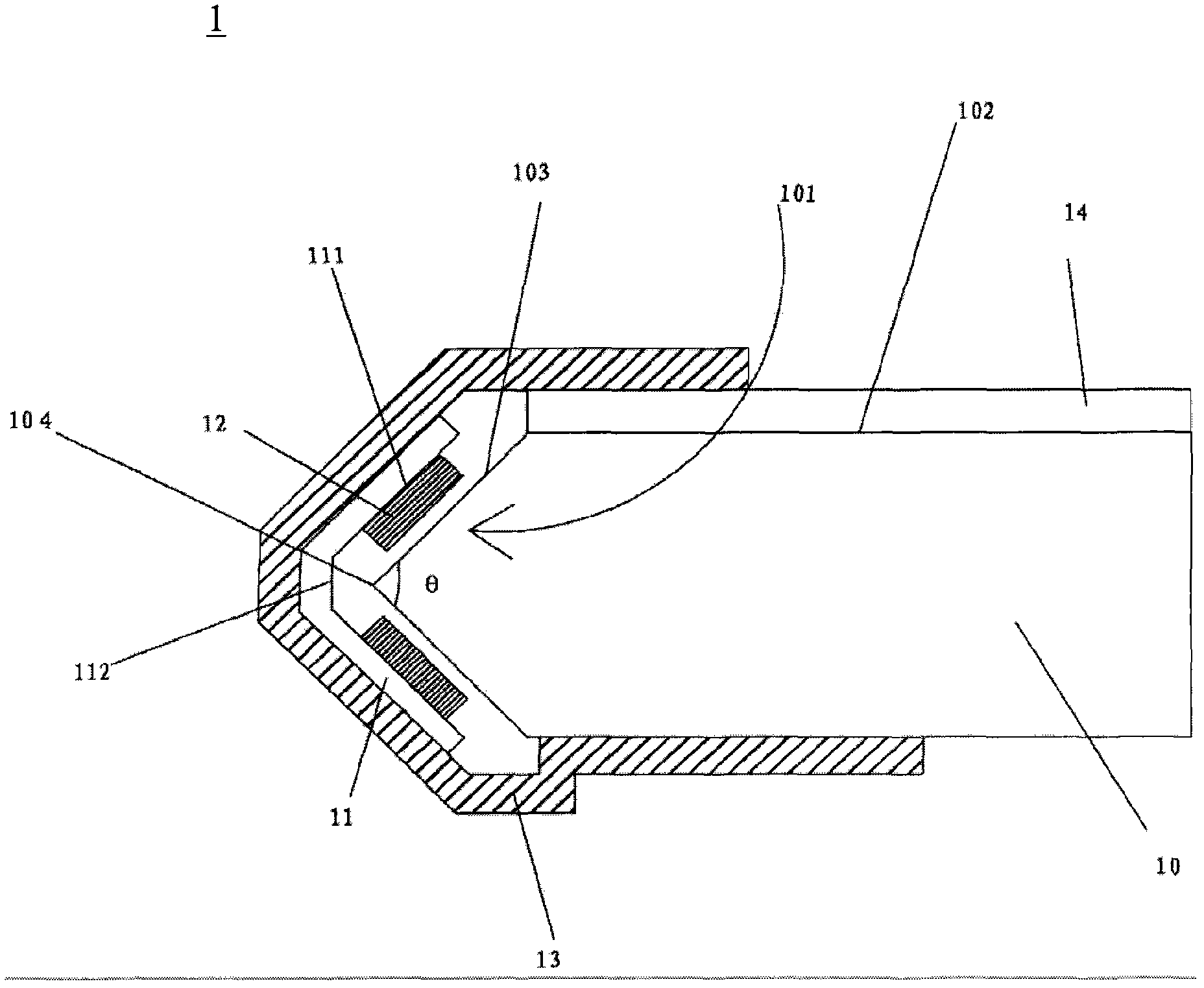
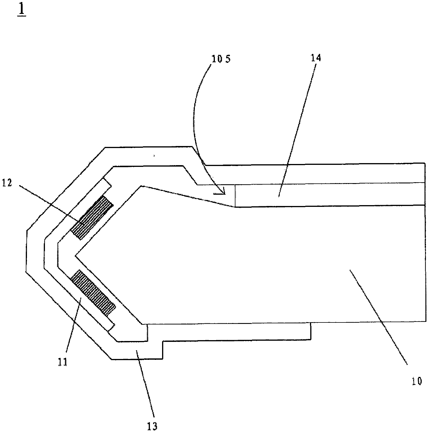
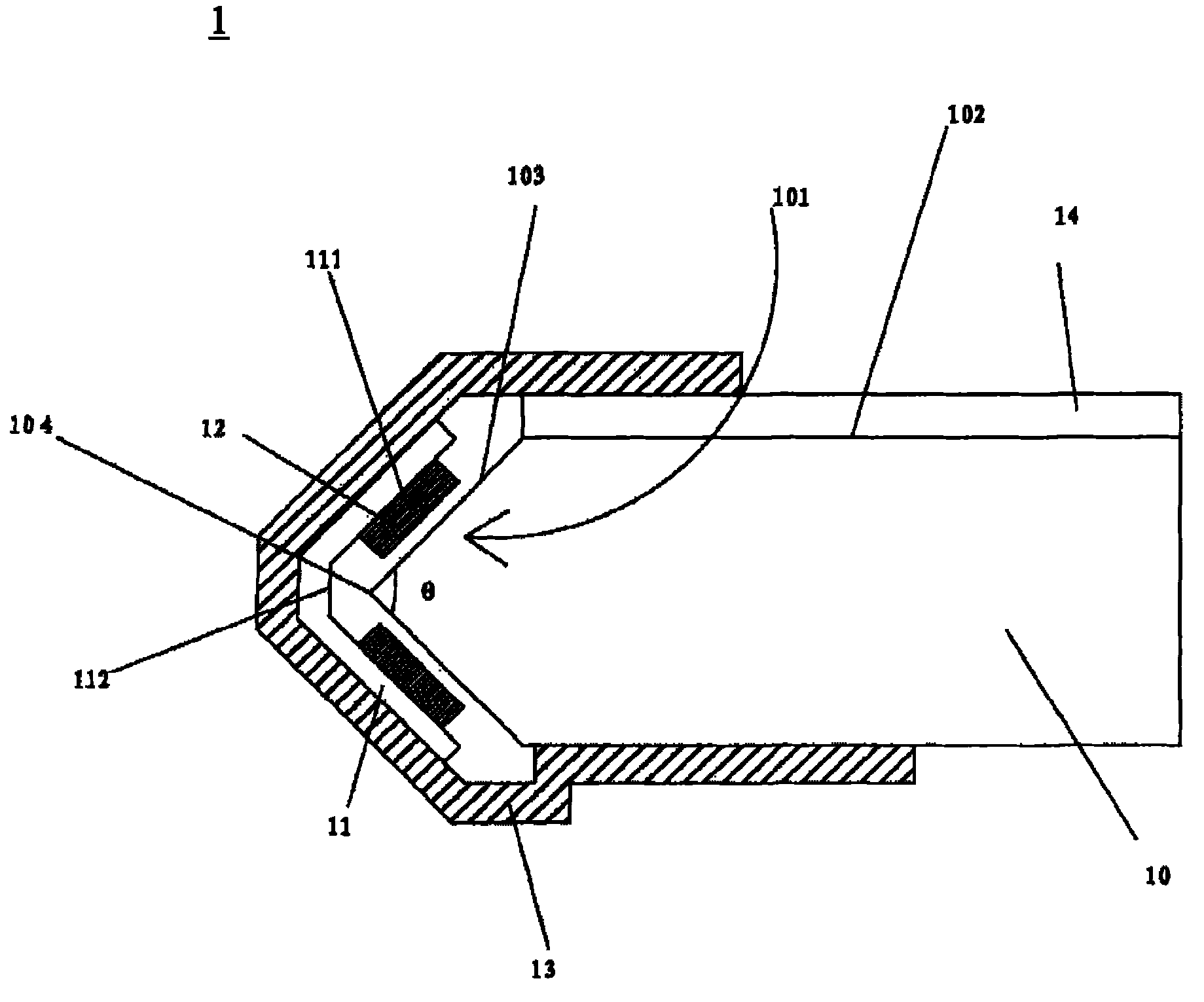
[0019] figure 1 A schematic structural diagram of a backlight module according to an embodiment of the present invention is shown. refer to figure 1 , The backlight module 1 includes: a light guide plate 10 , a circuit board 11 , a plurality of light sources 12 , an outer frame 13 and an optical film 14 . Wherein, the light guide plate 10 has a light incident surface 101 and a light exit surface 102, the light incident surface 101 is located on one side of the light guide plate 10, and is formed symmetrically by two first slopes 103, and the two first slopes 103 are connected to each other to form an included angle θ , in this embodiment, the included angle θ is a right angle, and in other embodiments, the included angle θ may be an acute angle. The light emitting surface 102 is a flat surface. The circuit board 11 cor...


PUM


Abstract

A backlight module comprises a light guide plate, a circuit board, a plurality of light sources, an outer frame and an optical film. The light guide plate is provided with a light input face and a light output face. The light input face is located on one side of the light guide plate and symmetrically formed by two first inclined planes. The two first inclined planes are mutually connected to form an included angle. The circuit board corresponds to the light input face of the light guide plate, and the plurality of light sources on two second inclined planes are arranged in staggered mode. The plurality of light sources are disposed on the second inclined planes of the circuit board and correspond to the first inclined planes. The outer frame is provided with a plurality of bends so as to form a containing space to match with the light guide plate and contain the circuit board, the light sources and the light guide plate. The optical film is arranged on the light output face of the light guide plate and contained inside the outer frame. The backlight module is capable of reducing weight, enabling emitted light to be more even and also enabling the light sources to correspond to the light guide plate well in position.

Description

technical field [0001] The invention relates to a backlight module, in particular to a backlight module with optical elements. Background technique [0002] The Back Light Unit (BLU for short) is one of the key components of the LCD panel. Its function is to supply sufficient brightness and uniformly distributed light source so that the LCD can display images normally. In order to display high-quality images, especially the birth of tablet computers, there is a higher requirement for the brightness of the backlight module. Backlight unit (BLU) can be divided into vertical type and side type. At present, in the side-type backlight module, the method of increasing the number of light-emitting diodes (LEDs) or entering light from both sides of the light guide plate is usually used to achieve high brightness. However, these methods will limit the optical performance or increase the number of backlight modules ( BLU) thickness. Another way is to install three-color light strip...

Claims


Application Information

Patent Timeline
Patent Type & Authority Applications(China)
IPC IPC(8): F21S8/00F21V8/00F21V19/00G02F1/13357F21Y101/02
Inventor 赵永贵
Owner AU OPTRONICS (SUZHOU) CORP LTD
Why Eureka
Try Eureka