Lamp shell with air flow diversion cooling effect

A heat dissipation and air diversion technology, applied in the field of lighting, can solve the problems that the heat conduction base panel cannot achieve auxiliary heat dissipation effect, burn the lamp body and circuit board, and gather in the middle of the lamp pool, etc., so as to facilitate the transfer of heat, The effect of extending the service life and ensuring the effect of long-term use

Active Publication Date: 2013-06-12
SHANGHAI QINSUN ELECTRIC CO LTD
View PDF4 Cites 0 Cited by
  • Summary
  • Abstract
  • Description
  • Claims
  • Application Information

AI Technical Summary

Problems solved by technology

In the structure of the heat dissipation system mentioned above, the heat conduction base plate in the center of the lamp pool can quickly absorb the heat generated by the LED lamp body and the circuit board, and directly radiate into the surrounding air through the heat dissipation scales on the upper surface, and the heat dissipation effect is good. However, the heat-conducting base plate outside the lamp pool cannot directly absorb the heat generated by the lamp body and the circuit board, but must conduct the absorbed heat from the lamp body through the heat-conducting base plate in the middle, so as to complete the heat radiation through the heat-dissipating scales , in this heat transfer process, when the middle heat conduction base plate conducts heat to the heat conduction base plate around the lamp pool, the heat has been gradually lost during the transfer process, and a large amount of heat is still gathered in the middle of the lamp pool, even Burning the lamp body and the circuit board, it can be seen that the extended heat conduction base panel does not have a good auxiliary heat dissipation effect, and also causes a waste of system cost
In the prior art, there is not a desirable good solution to solve this technical problem

Method used


Image

  • Lamp shell with air flow diversion cooling effect
  • Lamp shell with air flow diversion cooling effect

Examples


Embodiment Construction

[0016] The present invention will be described in further detail and completely below in conjunction with the accompanying drawings.

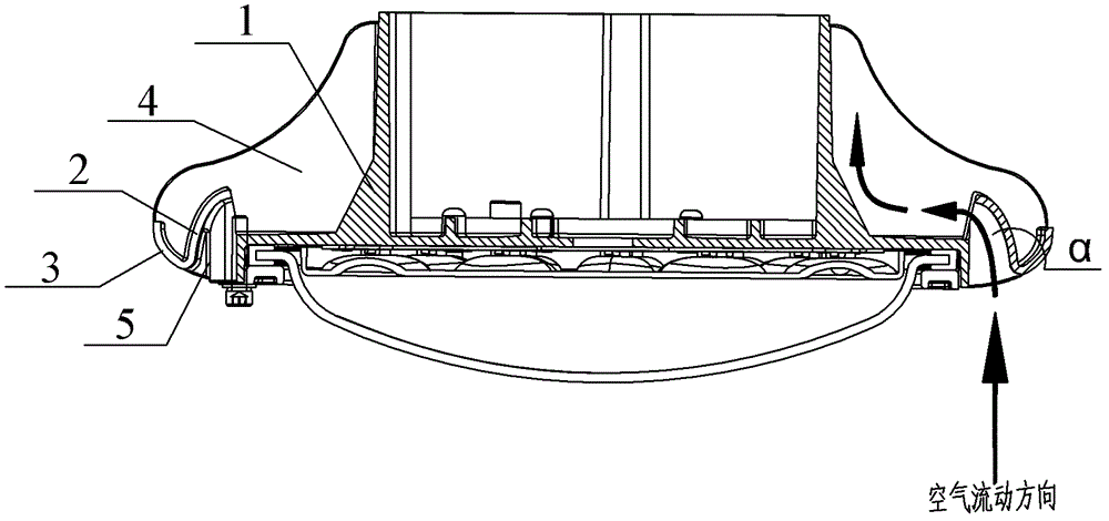
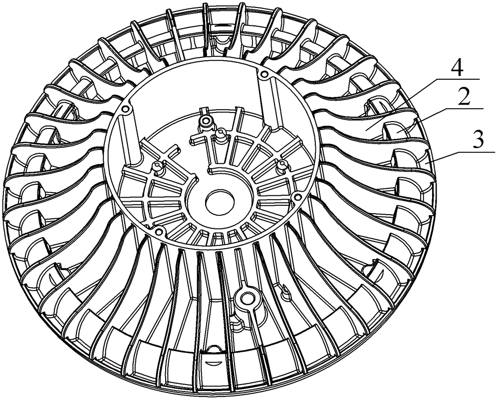
[0017] Such as figure 1 with figure 2 As shown: a lamp housing with air conduction and heat dissipation provided by the present invention is characterized in that: a guide member is provided on the circumference of the lamp housing 1, and the guide member is formed by an inward concave The arc-shaped deflector 2 is formed with the outwardly concave arc-shaped edge plate 3, and the formed section is obliquely hook-shaped; the angle α of the formed obliquely hook is preferably an acute angle; between the outer casing and the flow-guiding member Also be provided with some heat dissipation fins 4, and described heat dissipation fins 4 are evenly distributed in the circumference of housing; The groove that is formed by deflector plate is provided with some partition plates 5 on the inner side of housing, and described partition plate 5 and the po...


PUM


Abstract

The invention discloses a lamp shell with an air flow diversion cooling effect. The lamp shell is characterized in that the peripheric circle of the lamp shell is provided with a flow diversion member, the flow diversion member is formed by an inner concave circular arc guide plate and an outer concave circular arc edge plate, and a formed section is of an oblique hook shape; and a plurality of heat dissipation fins are arranged between an outer shell and the flow diversion members. In the invention, an upper-lower hollow-out interval space is arranged between adjacent heat dissipation fins due to the special shape of the flow diversion member, thus, the flow characteristic of the air is more fitted, thereby being beneficial to thermal diversion; the heat dissipation is not only realized through thermal radiation but also realized through accelerating air convection from bottom to top, and the heat dissipation efficiency is greatly improved; lower temperature raising can be obtained, and the temperature difference of a lamp hull and air is greatly reduced, and the service life of a lamp is prolonged;and in addition, the lamp shell provided by the invention has the advantages of simple shell structure, convenience in processing, and can easily realize scale production and has practical value.

Description

technical field [0001] The invention relates to a lamp housing structure, in particular to a lamp housing with air conduction and heat dissipation functions, and belongs to the technical field of lighting. Background technique [0002] In recent years, LED has been recognized by the society for its superior performance of high efficiency, energy saving, safety and reliability, and long life, and has been increasingly widely used. With the development of LED, the emergence of high-power LED with ultra-high brightness and white light emission has expanded the application field of LED to household lighting, urban and rural lighting projects and road lighting. Although the luminous efficiency of LED is very high, which is 2 to 2.5 times that of general high-pressure sodium lamps, a certain proportion of electrical energy will still be converted into heat energy during actual use. Moreover, high-power LED lamps are actually an application in which many single high-power LEDs are...

Claims


Application Information

Patent Timeline
Patent Type & Authority Patents(China)
IPC IPC(8): F21V29/00F21V29/74
Inventor 王旭辉李修章孙尚鹏于锡友
Owner SHANGHAI QINSUN ELECTRIC CO LTD
Why Eureka
Try Eureka