Charging method of centralized charging rack for battery box of electric vehicle charging and battery-changing station

A technology of charging and swapping stations and electric vehicles, which is applied in the direction of secondary battery charging/discharging, electric vehicles, battery circuit devices, etc., can solve the problems of untimely discovery, poor scalability, unbalanced force, etc., and achieve fast replacement efficiency and Effects of safety assurance, prevention of fire or explosion accidents, and saving of transportation time

Inactive Publication Date: 2012-05-02
STATE GRID CORP OF CHINA +1
View PDF2 Cites 6 Cited by
  • Summary
  • Abstract
  • Description
  • Claims
  • Application Information

AI Technical Summary

Problems solved by technology

[0005] (1) There are design defects in the battery box charging rack, low load capacity, unbalanced force, poor scalability, and poor heat dissipation of the battery box charging rack, which may easily cause the temperature of the battery box to be too high
[0006] (2) The battery box charging rack lacks a real-time monitoring device. During the charging process, the battery box has a short circuit or open circuit problem, which cannot be detected in time, and the abnormal state of the battery box cannot be observed in real time.
[0007] (3) When the charging stand and the battery box quick-change robot are used together, the quick battery-change robot needs to rotate a circle along the circular track, the movement distance is long, and the battery box replacement time is long, which delays the replacement efficiency of the battery box of the electric vehicle

Method used


Image

  • Charging method of centralized charging rack for battery box of electric vehicle charging and battery-changing station
  • Charging method of centralized charging rack for battery box of electric vehicle charging and battery-changing station
  • Charging method of centralized charging rack for battery box of electric vehicle charging and battery-changing station

Examples


Embodiment Construction

[0026] The present invention will be described in further detail below in conjunction with the accompanying drawings and specific embodiments.

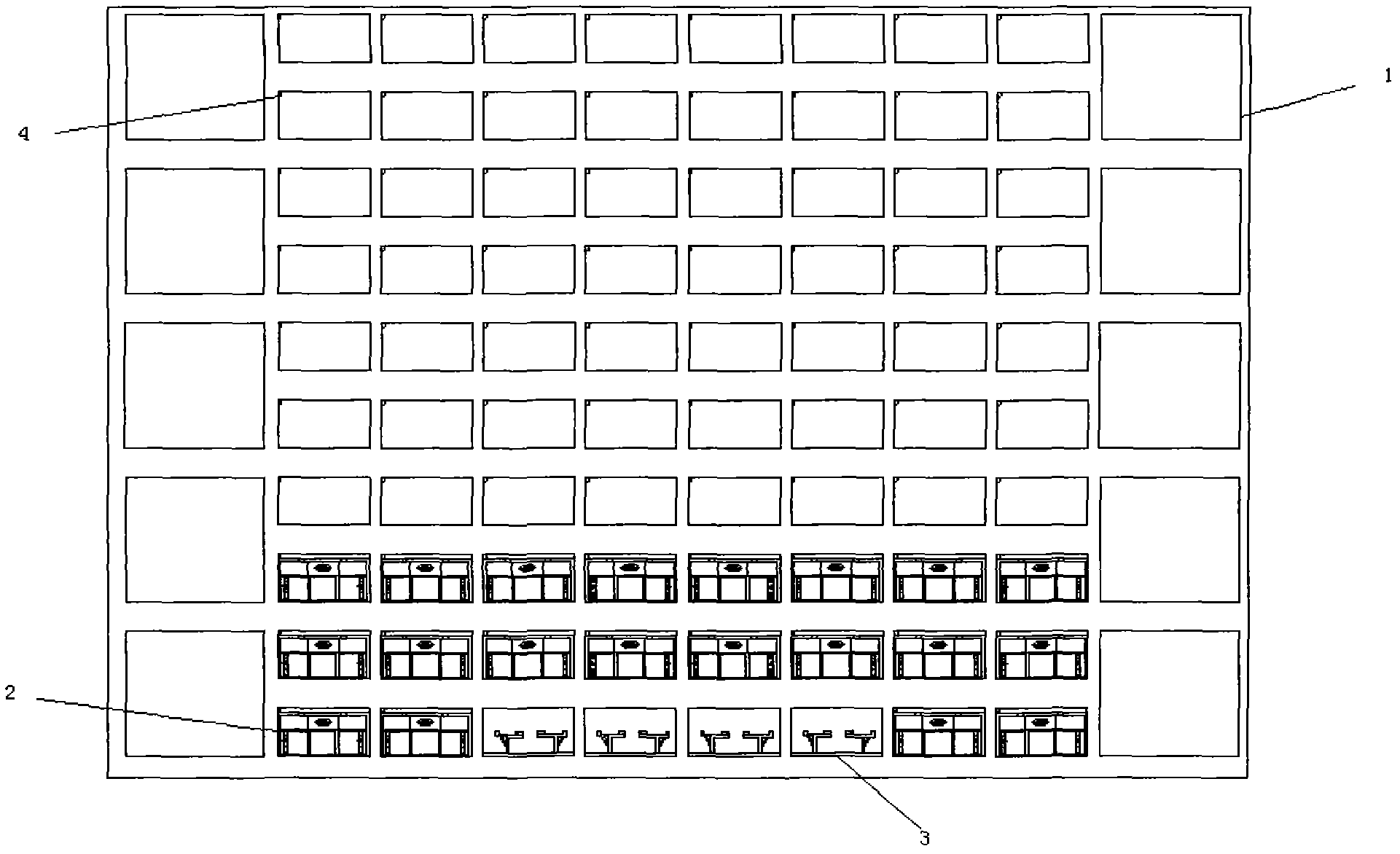
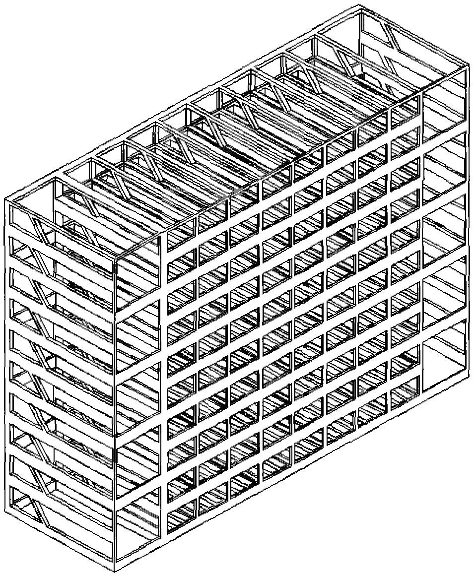
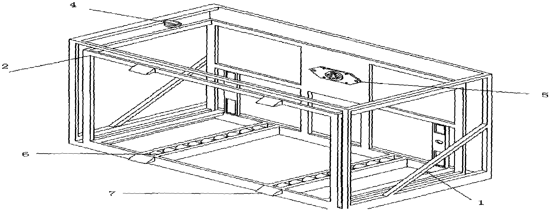
[0027] refer to Figure 1 to Figure 5 , a centralized charging rack for battery boxes in electric vehicle charging and swapping stations, including a support frame 1, a plurality of independent charging frames 2 for charging the battery boxes, a battery box transfer platform 3, and a composite temperature-sensing smoke detector 4. The support frame 1 is distributed on both sides and the bottom of the charging frame 2, and supports the battery box. The charging frames 2 are evenly distributed on the charging frame; each charging frame 2 is provided with a charging connector 5 inside the rear, and the bottom of the charging frame 2 is provided with two rows of first guide wheels 6 for supporting and transferring the battery box 8 to the charging connection On the charger 5, a charging status indicator light is provided on the outside o...


PUM


Abstract

The invention relates to a charging method of a centralized charging rack for a battery box of an electric vehicle charging and battery-changing station. The charging rack comprises a plurality of support frames, a plurality of independent charging frames for charging the battery box, a plurality of battery box transfer platforms, a plurality of composite temperature/smoke-sensitive detectors and a charging state indicator light; the support frames are arranged on the two sides and at the bottoms of the charging frames; the charging frames are uniformly arranged on the charging rack in a plurality of lines and rows; the battery box transfer platforms are arranged at the bottom of the centralized charging rack for the battery box; and the composite temperature/smoke-sensitive detectors are arranged on one sides of the top parts of the charging frames and are connected with the support frames through bolts. The method has the advantages of high bearing capacity, high efficiency of battery box replacement and high safety, charging abnormalities can be found promptly, the safe operation of the charging rack for the battery box can be ensured and higher replacement efficiency and security guarantee can be provided for the electric vehicle charging and battery-changing station.

Description

technical field [0001] The invention relates to a charging method for a centralized charging rack of a battery box, in particular to a charging method for a centralized charging rack for a battery box of an electric vehicle charging and swapping station. Background technique [0002] With the maturity of electric vehicle charging and swapping technology and the large-scale promotion and use of electric vehicles, more and more centralized charging racks for battery boxes are used. However, the charging stand in the prior art has poor carrying capacity, and the replacement of rechargeable batteries is inefficient, and cannot meet the demand for a large number of charging and battery replacement. [0003] The application number is 201010198324.2 for the invention patent "a battery charging rack". However, this charging rack is not equipped with a support frame, and the battery box has a poor bearing capacity, and it is not equipped with a composite temperature-sensing smoke det...

Claims


Application Information

Patent Timeline
Patent Type & Authority Applications(China)
IPC IPC(8): H01M10/44H02J7/00
CPCY02E60/12Y02E60/10
Inventor 魏洪昌何健陈暴默张平刘文鹏
Owner STATE GRID CORP OF CHINA
Why Eureka
Try Eureka