

Current sensor mounting structure
A technology of current sensor and installation structure, which is applied in the direction of switchgear, electrical components, busbar/line layout, etc., which can solve the problems of inconvenient operation, hidden danger of current sensor replacement and maintenance accidents, low replacement and maintenance efficiency, etc.
Inactive Publication Date: 2012-05-02
CRRC YONGJI ELECTRIC CO LTD
View PDF3 Cites 0 Cited by
- Summary
- Abstract
- Description
- Claims
- Application Information
AI Technical Summary
Problems solved by technology
[0003] In order to solve the problems that the installation structure of the existing current sensor causes difficulty in replacement and maintenance of the current sensor and low efficiency of replacement and maintenance during the use process, as well as the problems of potential accidents and inconvenient operation that are likely to be caused during the replacement and maintenance of the current sensor, a method is provided. A Current Sensor Mounting Structure
Method used
View moreImage
Smart ImageViewing Examples

Examples
Embodiment Construction
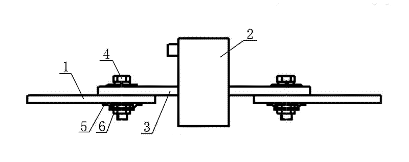
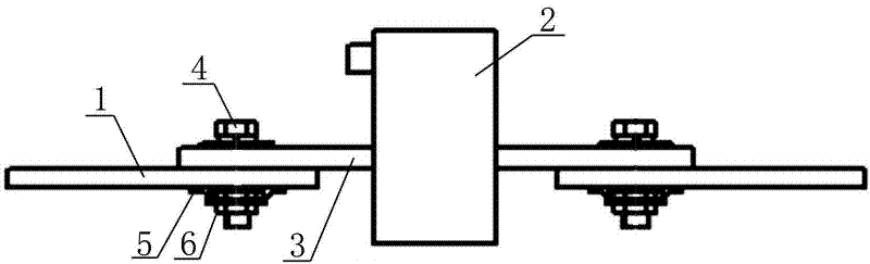
[0010] A current sensor installation structure, including a main side copper bar 1 and a current sensor 2; also includes a special installation copper bar 3; the current sensor 2 is installed through the special installation copper bar 3; both ends of the special installation copper bar 3 are installed through the Fixing bolts 4; the number of copper bars 1 on the main side is two; one end of the two main side copper bars 1 is fixed with a pressure plate 5, and the surface of the pressure plate 5 is installed with a cage nut 6; The bolts 4 respectively pass through the cage nuts 6 installed on the two main side copper bars 1 .
Login to View More PUM
 Abstract
The invention relates to a mounting structure of a current sensor, in particular to a current sensor mounting structure, solving the problems of the existing current sensor mounting structure that a current sensor cannot be easily replaced and maintained in use, the efficiency of replacement and maintenance is low, hidden accident risks and inconvenient operation can be easily caused in replacement and maintenance of the current sensor. The current sensor mounting structure comprises two primary side copper bars, a current sensor and a special mounting copper bar; the current sensor is arranged on the special mounting copper bar in a penetrating way; the two ends of the special mounting copper bar are respectively provided with a fixing bolt in a penetrating way. The problems of the existing current sensor mounting structure such as difficulties in replacement and maintenance of the current sensor in use, low efficiency of replacement and maintenance, hidden accident risks caused easily in replacement and maintenance of the current sensor and inconvenient operation can be solved effectively.
Description
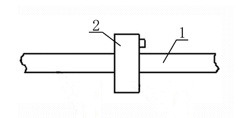
technical field [0001] The invention relates to a mounting structure of a current sensor, in particular to a mounting structure of a current sensor. Background technique [0002] Current sensors are commonly used components for collecting current signals in modern electric transmission systems, and are widely used. The installation structure of the current sensor is generally divided into two types: the cable penetration installation structure and the copper bar penetration installation structure. With the continuous development of the electric transmission system, the power of the device continues to increase, and the rated operating current also increases accordingly. The through-type installation structure of copper bars has gradually become the mainstream. The existing copper bar penetrating installation structure mainly includes the main side copper bar 1, the current sensor 2 is installed through the main side copper bar 1, and the two ends of the main side copper bar...
Claims
Login to View More Application Information
Patent Timeline
 Patent Type & AuthorityApplications(China)
IPC IPC(8): H02B1/20H02B3/00
Inventor刘立刚王彬孙湘漪马连凤
OwnerCRRC YONGJI ELECTRIC CO LTD