Slider device for fixing housing of electric installation device to rail, has connecting region with insulating element for covering conductive contact element of electric installation device

A sliding device and shell technology, applied in the direction of coupling devices, components of connecting devices, details of substation/switch layout, etc., can solve the problems of installation workers or users, and achieve the effect of saving parts or materials

Active Publication Date: 2012-05-02
SIEMENS AG
View PDF4 Cites 5 Cited by
  • Summary
  • Abstract
  • Description
  • Claims
  • Application Information

AI Technical Summary

Problems solved by technology

Clamping screws or clamping pressure pieces are located directly behind the housing opening and can be accessed by the installer or the user if the user, for example, assembles or disassembles other equipment step by step or clamps or loosens conductors

Method used


Image

  • Slider device for fixing housing of electric installation device to rail, has connecting region with insulating element for covering conductive contact element of electric installation device
  • Slider device for fixing housing of electric installation device to rail, has connecting region with insulating element for covering conductive contact element of electric installation device
  • Slider device for fixing housing of electric installation device to rail, has connecting region with insulating element for covering conductive contact element of electric installation device

Examples


Embodiment Construction

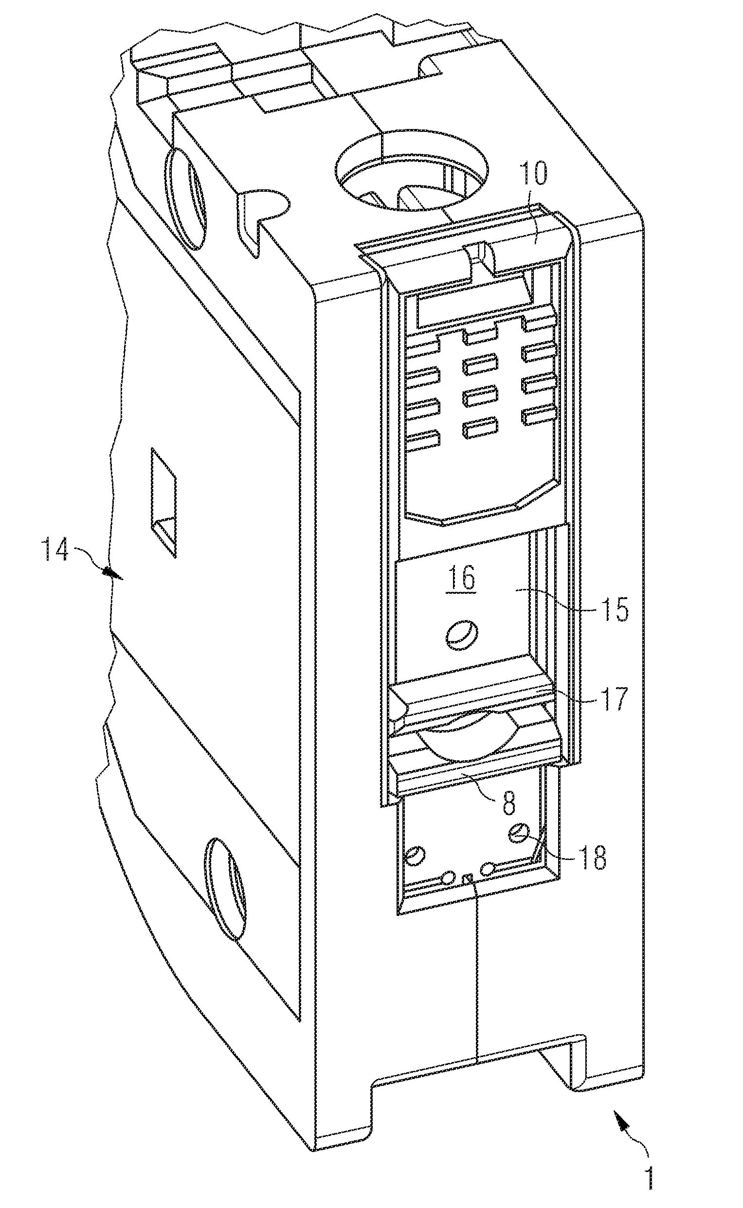
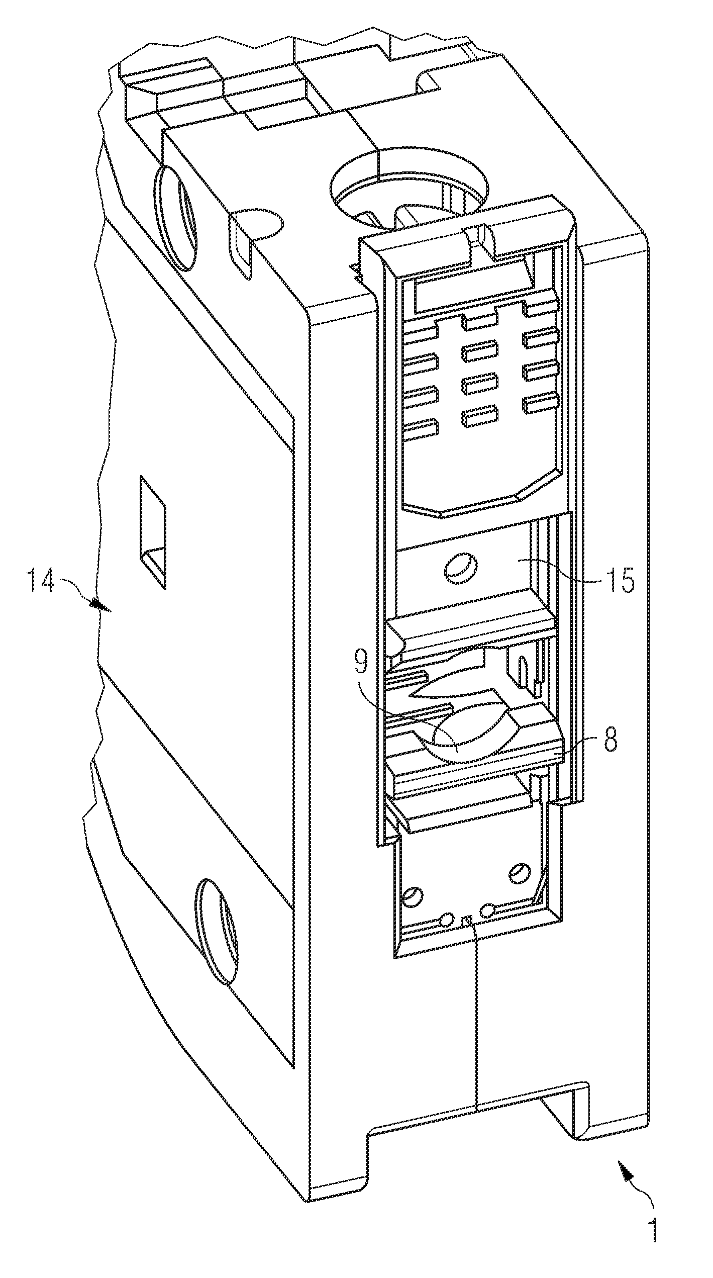
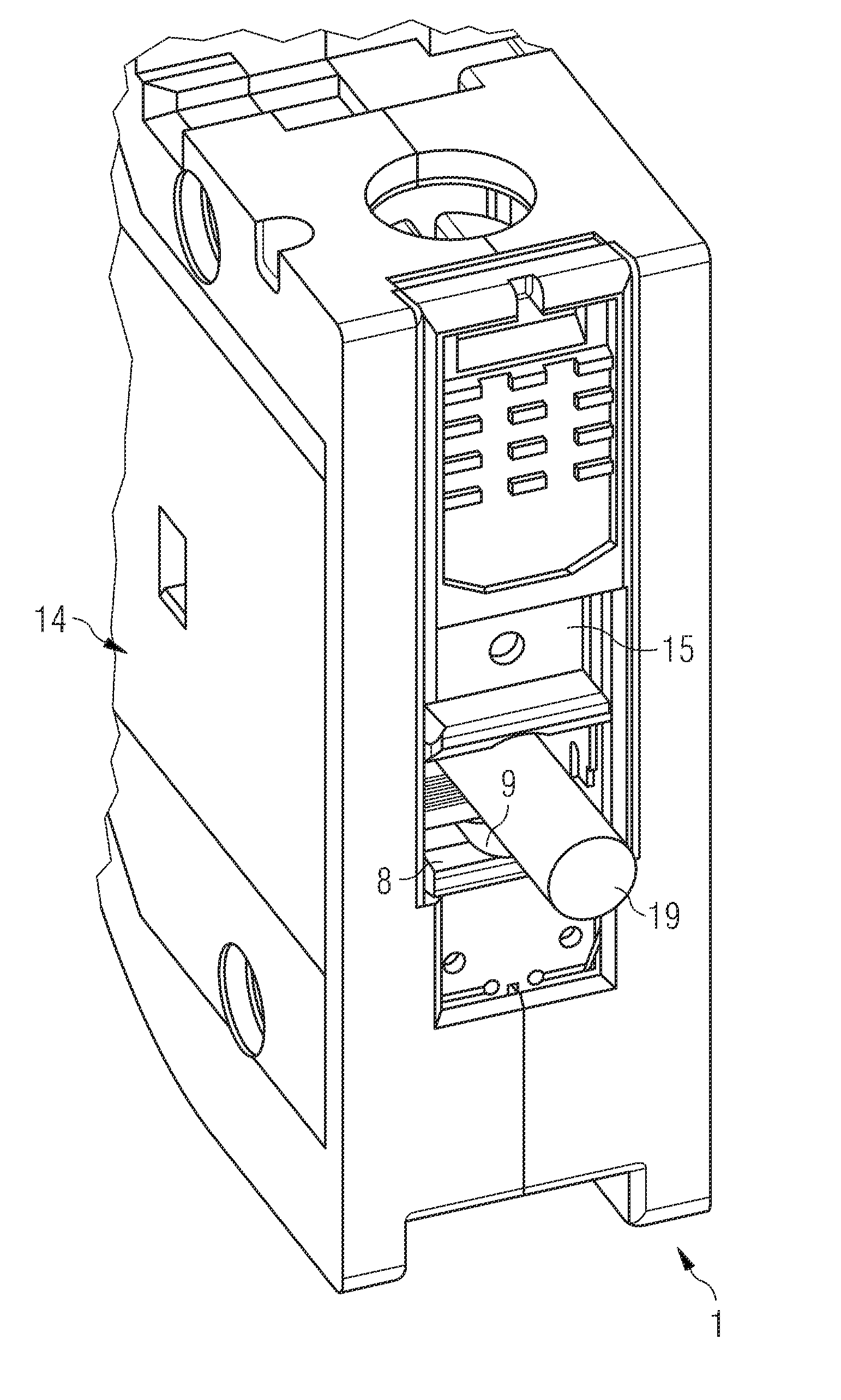
[0027] figure 1 A sliding device 1 according to the invention is shown which is preferably L-shaped and has two sides 2 , 3 which are arranged at an angle of preferably approximately 90° to one another. The sliding device 1 is composed of two preferably L-shaped guide plates 4 , 5 running parallel to one another, which are connected to one another in the region of the side legs 3 via a connecting section 6 . Via this connection section 6 the slide device 1 is formed U-shaped in the area of ​​the side leg 3 and serves as locking element 12 . Arranged between the U-shaped legs 3 is a preferably meander-shaped spring element 13 which is preferably integrally formed on the locking element 12 and forms a spring-like structure. The elastic element 13 can be prestressed, so that a force effect for interlocking or securing the series of mounting devices is reliably formed.

[0028] The U-shaped side leg 3 transitions into the side leg 2 via a connection point 7 , which is preferably...


PUM


Abstract

The slider device (1) has actuating element (10), locking element (12) and connecting region (7) between actuating element and locking element. The connecting region is provided with an insulating element for covering a conductive contact element of electric installation device. The insulating element is provided with a web like projection.

Description

technical field [0001] The invention relates to a sliding device for fixing a housing on a guide rail, comprising an actuating element, a locking element and a connecting point between the actuating element and the locking element. Background technique [0002] Such sliding devices are used in combination with series mounting devices (Reiheneinbaugeröt), in particular with switches in busbar assemblies. In this series, the mounting device has a housing which has an advantageous shape for busbar assembly. In this case, the assembly of the series of mounting devices is simplified in that the housing of the series of mounting devices, for example composed of switches or protective switches, permits a flat arrangement of other housings on two or more sides. [0003] Such a switch or protective switch is fastened to the top hat rail by means of a slide. The problem is that the top-hat rail is arranged on the side facing away from the user when the switch is in use, and the swit...

Claims


Application Information

Patent Timeline
Patent Type & Authority Applications(China)
IPC IPC(8): H05K5/02H01H9/04
CPCH02B1/0523H01R13/447H01R9/26H02B1/14H02B1/0526
Inventor S.马拉特A.帕蒂尔A.赖内尔特
Owner SIEMENS AG
Why Eureka
Try Eureka