Spindle motor

A technology of lead screw motor and lead screw, which is applied in the direction of electromechanical devices, electrical components, mechanical equipment, etc., can solve the problems of short service life and achieve the effect of saving costs and parts

Active Publication Date: 2011-05-04
SEW-EURODRIVE GMBH & CO KG
View PDF4 Cites 19 Cited by
  • Summary
  • Abstract
  • Description
  • Claims
  • Application Information

AI Technical Summary

Problems solved by technology

[0002] A lead screw motor is known from DE 10235078 A1, which has a limited grease volume and therefore a short service life

Method used


Image

  • Spindle motor
  • Spindle motor
  • Spindle motor

Examples


Embodiment Construction

[0074] The present invention is now described in detail with the aid of the accompanying drawings:

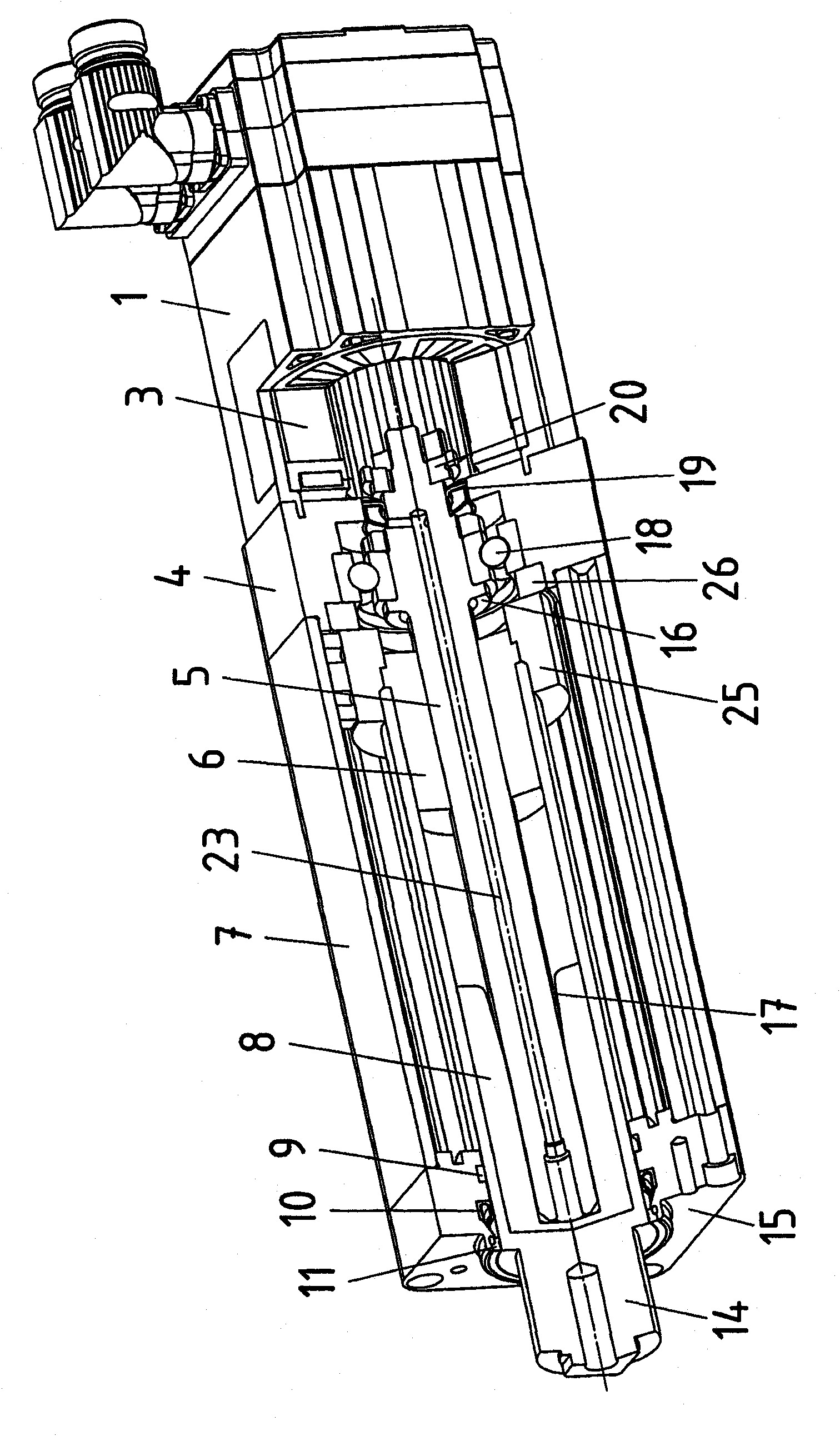
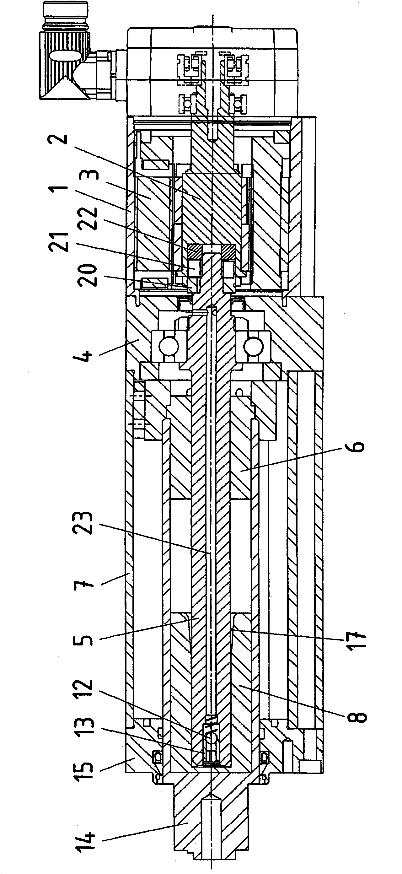
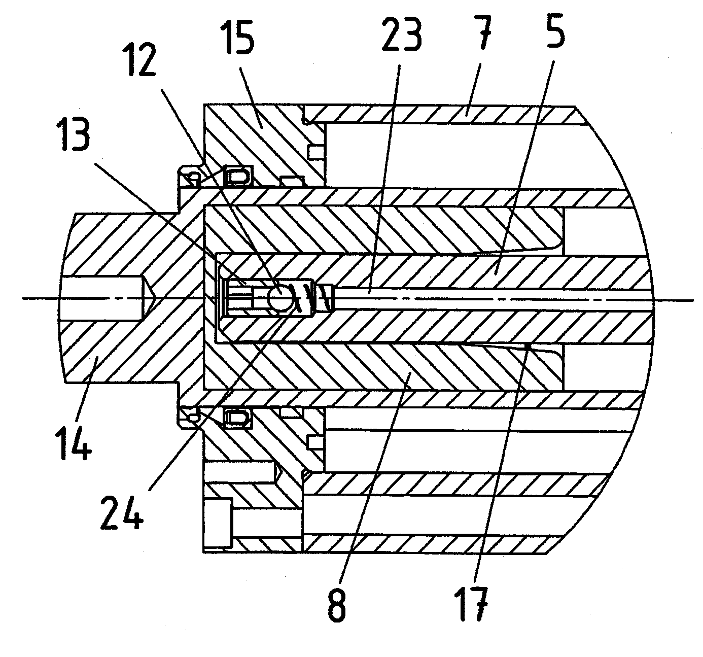
[0075] exist figure 1 The lead screw motor of the present invention is shown in a cut oblique view, in Figure 1a The lead screw motor of the present invention is shown in cross-sectional view. exist figure 2 with image 3 are enlarged and shown in Figure 1a Partial view of the lead screw motor in .

[0076] The housing parts 4 , 7 and 15 of the spindle motor are connected sealingly to the motor housing 1 of the motor comprising the rotor 2 and the stator 3 . An O-ring is preferably inserted at each connection point of the housing parts in order to ensure tightness even at overpressures of greater than, for example, 2 bar.

[0077] Housing part 4 accommodates a bearing 18 via which spindle 5 is supported. The lead screw is connected to the rotor shaft 2 via an axially pluggable coupling. The coupling has a claw 20 and a claw 22 between which a plastic star 21 is arran...


PUM


Abstract

The invention relates to a spindle motor, comprising an electric motor having a rotor connected to a threaded spindle, the thread of which is engaged with a thread of a spindle nut connected to a piston rod, wherein the spindle nut, along with the piston rod, is axially guided in a housing part, a guide part is connected to the spindle nut and piston rod for axially guiding the same, and wherein the threaded spindle is mounted by means of a bearing in the housing part or in a second housing part connected to the first housing part, a cooling channel being configured in the housing part, in particular a cooling channel which extends in the circumferential direction.

Description

technical field [0001] The invention relates to a screw motor. Background technique [0002] A screw motor is known from DE 10235078 A1, which has a limited grease volume and therefore has a short service life. [0003] A screw motor is known from DE102007014714, which has the figure 2 Lubricant input line 21 shown in . The screw motor must be relubricated regularly. [0004] High-pressure seals for use in the specialized field of hydraulic systems are known from the product catalog of the company Dichtomatik, for example PTFE groove seals with steel V-shaped springs (designated MA47 there). In addition, another high-pressure seal is known, such as the product WCP21, which is presented as a radial shaft seal with a PTFE sealing lip and an elastomer pre-tensioning disk, which are clamped between two metal cages. Contents of the invention [0005] It is therefore the object of the invention to prolong the service life of the lead screw motor. [0006] According to the ...

Claims


Application Information

Patent Timeline
Patent Type & Authority Applications(China)
IPC IPC(8): H02K7/06B23Q5/40B23Q11/12F16H25/20H02K5/20H02K9/19
CPCB23Q5/40B23Q11/127F16H57/0415F16H57/0497F16H2025/2031F16H2025/2075H02K7/06H02K7/083H02K5/203
Inventor G·迪特斯J·贝克尔M·加布里尔
Owner SEW-EURODRIVE GMBH & CO KG
Why Eureka
Try Eureka