Compressive sprayer

A sprayer and compressed technology, applied in the field of compressed sprayers, can solve the problems of pesticide spillage, short service life, and affecting personal safety

Active Publication Date: 2012-05-09
SEESA HLDG
View PDF4 Cites 7 Cited by
  • Summary
  • Abstract
  • Description
  • Claims
  • Application Information

AI Technical Summary

Problems solved by technology

When carrying, lift the handle, the stop rod hangs on the lifting lug, and the liquid bucket can be lifted; when unscrewing the lid, make the stop rod of the handle withdraw from the lifting lug, rotate to the back side of the lifting lug, press the lifting lug, and drive the lid to rotate, Opening the lid, this knotting bucket is simple and convenient, but this structure is only suitable for the lid of the small mouth of the barrel, and the lifting lug of the opening is only connected to the lid on one side. When lifting, it must support the self-weight and rated The capacity of water is heavy, and when locking or unscrewing the lid, it has to bear the torque after the thread is locked. product appearance
When the operator does not spray after inflating for many times, the barrel may burst and other serious consequences may occur because the internal air pressure value exceeds the bearing capacity of the barrel, and after the spraying is completed, if the pressure is not fully released, the barrel cannot be opened directly Otherwise, it will cause pesticide spillage and affect personal safety. If the pressure is to be fully relieved, most of the existing technologies continue to spray to release the air pressure in the barrel, which is very troublesome and wasteful. Therefore, someone designed a safety valve. However, most of the existing safety ...

Method used


Image

  • Compressive sprayer
  • Compressive sprayer
  • Compressive sprayer

Examples


Embodiment Construction

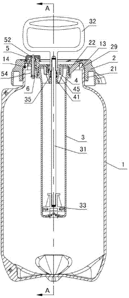
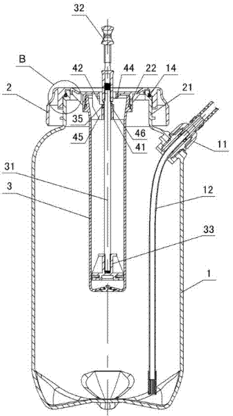
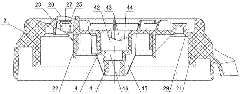
[0016] The present invention relates to a compressed sprayer, such as Figure 1-Figure 9As shown, it includes a barrel body 1 and a barrel cover 2, a safety valve device is arranged on the barrel cover, and a connecting ring 21, an installation ring 22 and a handle screw clamping mechanism are formed in the barrel cover, and the connecting ring of the barrel cover and the opening of the barrel body There is a sealing device between the parts, the connecting ring is formed with an internal thread, the internal thread is connected with the external thread of the mouth of the barrel body 1, the installation ring is connected with the pump 3, and the pumping rod 31 is installed in the bucket cover, and the pumping rod has a pumping handle 32 , the piston 33 is installed under the inflating rod, the piston matches with the inner wall of the air cylinder 3, the water suction pipe joint 11 is installed on the staving, the water suction pipe 12 is installed in the water suction pipe jo...


PUM


Abstract

A compressive sprayer comprises a barrel and a barrel cover. A safety valve device is arranged on the barrel cover, a connecting ring, a mounting ring and a handle screw clamping mechanism are arranged in the barrel cover, a sealing device is reserved between the connecting ring and an opening of the barrel, the connecting ring is connected with the opening of the barrel in a threaded manner, themounting ring is connected with an air cylinder, an air filling handle is arranged on an air filling bar in the barrel cover, a piston mounted below the air filling bar is matched with the air cylinder, a water suction pipe is mounted in a water suction pipe connector mounted on the barrel body, the handle screw clamping mechanism comprises a guide pipe arranged below a sink which is arranged in the barrel cover, a reinforcing plate is arranged outside the sink and the guide pipe, a spiral clamping groove is arranged on a sink wall, a stopper bar arranged at the lower end of the air filling handle is matched with the spiral clamping groove, the safety valve device comprises a mount arranged on the barrel cover, an inclined slide, a smooth slide and a groove are arranged on the mount, a valve hole is reserved in the mount, a slider arranged below a valve bonnet is matched with the inclined slide, a valve stem below the valve bonnet is provided with a seal ring in contact with an upper opening of the valve hole, a spring is arranged outside the valve stem, a snap ring is mounted in a snap groove arranged on the lower portion of the valve stem, and the snap ring is clamped into the snap groove to contact with the spring.

Description

technical field [0001] The present invention relates to nebulizers, and in particular to compression nebulizers. Background technique [0002] Commonly used sprayers can be divided into manual sprayers and motorized sprayers according to different power sources, and manual sprayers can be divided into non-inflatable liquid pump sprayers and pneumatic compression sprayers. The compression sprayer is a manual pump that injects air into the liquid barrel and accumulates pressure, which then leads to continuous spraying for a period of time. When the pressure in the spraying barrel decreases, the operator manipulates the manual pump again to pressurize. When the internal pressure of the liquid barrel is high, in order to allow the air pressure in the pump to fully enter the liquid barrel, the handle of the pump must be locked at its fully inserted position to prevent it from slipping. During storage and carrying, the handle of the pump must also be locked at its fully inserted p...

Claims


Application Information

Patent Timeline
IPC IPC(8): A01M7/00
Inventor 李冠军
Owner SEESA HLDG
Why Eureka
Try Eureka