
Automatic smooth pin pulling and assembling device

A compliant and automatic technology, applied in metal processing, metal processing equipment, manufacturing tools, etc., can solve the problems of uncontrollable twisting torque, failure to pull out, pin head cannot be twisted in, pin thread damage, etc., to achieve easy operation, The effect of avoiding human intervention and low cost

Inactive Publication Date: 2012-05-09
CHINA PRECISION ENG INST FOR AIRCRAFT IND AVIC
View PDF6 Cites 2 Cited by
  • Summary
  • Abstract
  • Description
  • Claims
  • Application Information

AI Technical Summary

Problems solved by technology

[0004] The disadvantage of the existing pin pulling method is that during the pin pulling process, the twisting torque of the pin head to the pin thread (the thread at the tail of the pin) cannot be controlled, or the pulling and mounting pin head is not aligned with the pin thread, resulting in If the torque is too large, the thread of the pin will be damaged, which will lead to the failure of pulling and installing the pin head, and the failure of pulling the pin.

Method used


Image

  • Automatic smooth pin pulling and assembling device
  • Automatic smooth pin pulling and assembling device
  • Automatic smooth pin pulling and assembling device

Examples


Embodiment Construction

[0020] The technical solution of the invention will be further described in detail below in conjunction with the accompanying drawings and embodiments:

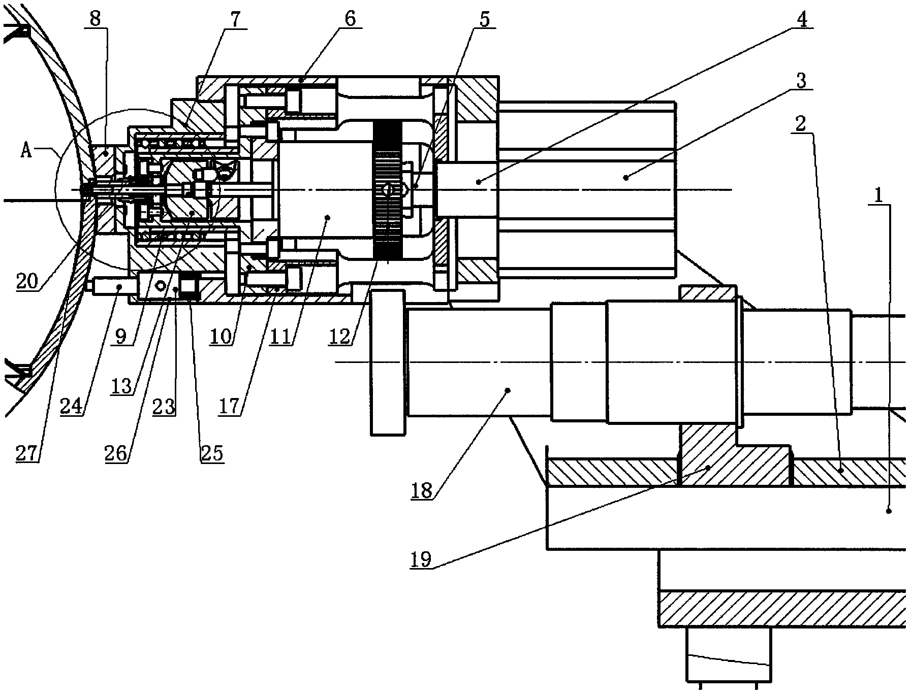
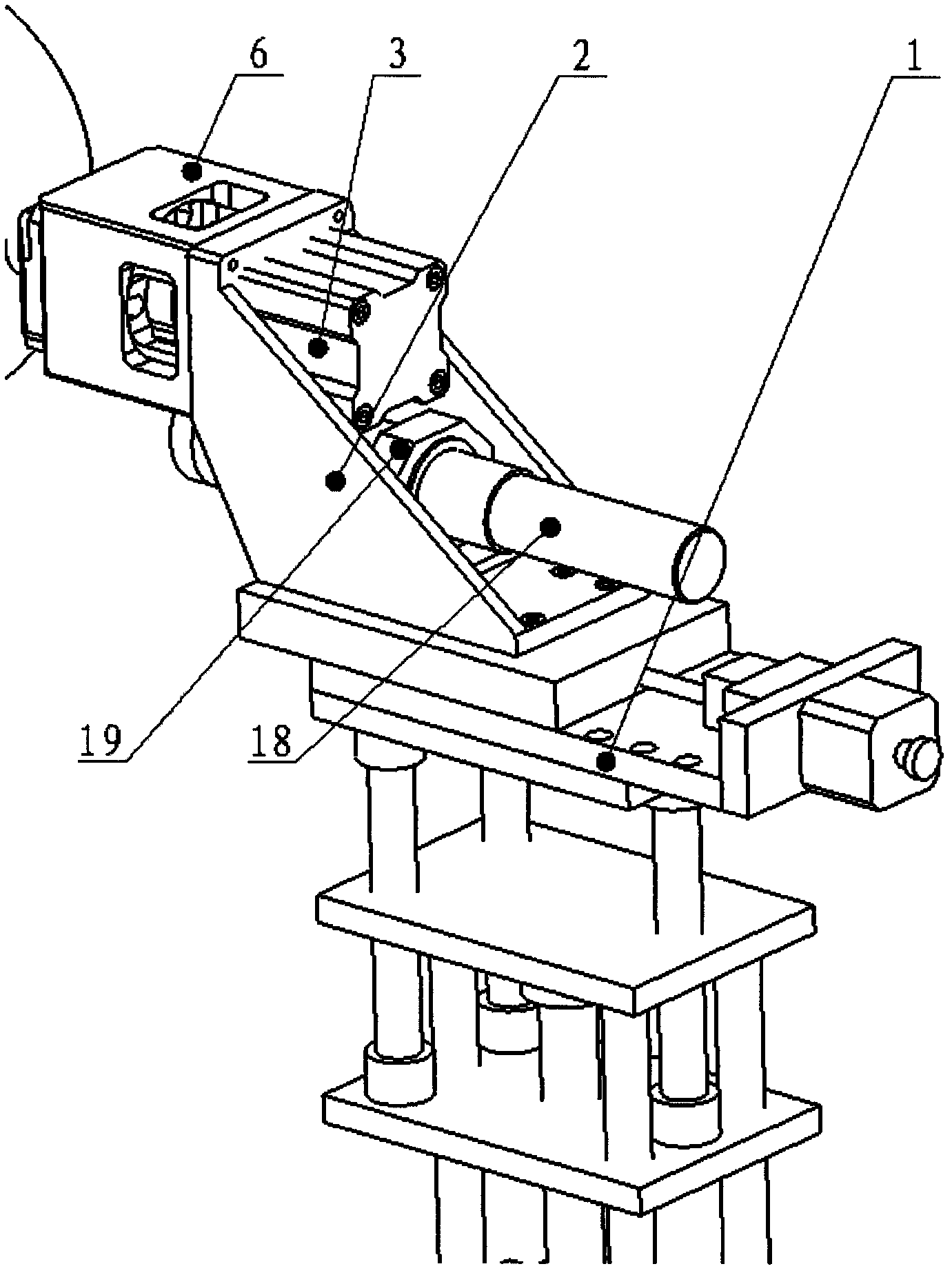
[0021] See attached Figure 2-8 As shown, this kind of automatic pliable pulling and pin loading device is characterized in that: the device includes an adjustment platform 1, the fixed bracket 2 is installed on the adjustment platform 1, and can move horizontally on the adjustment platform 1, and the fixed bracket 2 A cylinder 3 is installed at the rear, and an impact block 5 is fixed at the front end of the piston rod 4 of the cylinder 3;

[0022] A front fixed mount 6 is installed at the front end of the fixed bracket 2, a centering support 7 is installed at the front end of the front fixed mount 6, and a workpiece positioning block 8 is installed at the front end of the centering support 7;

[0023] Set a linear bearing 9 in the center hole of the centering bracket 7, set a guide bracket 10 on the inner hole of the linea...


PUM


Abstract

The invention discloses an automatic smooth pin pulling and assembling device. The device comprises an adjustment platform; a fixing bracket is mounted on the adjustment platform and can move horizontally on the adjustment platform; a cylinder is mounted at the rear part of the fixing bracket; an impact block is fixed at the front end of a piston rod of the cylinder; a front fixing frame is mounted at the front end of the fixing bracket; a centering bracket is mounted at the front end of the front fixing frame; a workpiece positioning block is mounted at the front end of the centering bracket; a linear bearing is sleeved in a center hole of the centering bracket; a guide bracket is sleeved in an inner hole of the linear bearing; a motor is mounted at the rear part of the guide bracket; a hand wheel is mounted on a rear output shaft of the motor; a front output shaft of the motor is connected with a second component of a clutch mechanism; a pin pulling and assembling pin head screw is fixed in the center hole of a first component of the clutch mechanism; and a drive source bracket bearing the backward impact force of the impact block is further fixed at the rear part of the guide bracket. The device avoids damage to pin thread in the twisting stage for pulling and assembling the pin head, is simple, convenient and quick to operate, is low in cost; moreover, the impact force of the traditional pin pulling mechanism is replaced with cylinder force.

Description

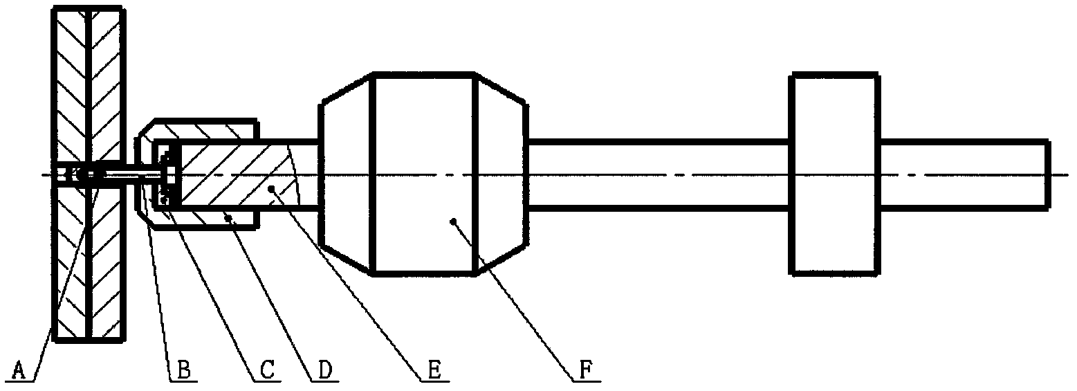
technical field [0001] The invention is an automatic flexible pulling and pinning device, which belongs to the technical field of product structure. Background technique [0002] Due to the high positioning accuracy of pins, they are widely used in modern precision machine tools. In the process of machine tool debugging, maintenance or repair, pulling out pins is a relatively common process. Once the pins fail to pull out, the above debugging or maintenance work will be canceled. Therefore, the seemingly simple process of pulling out pins cannot fail to attract our attention. [0003] The traditional withdrawal structure such as figure 1 As shown, the pulling and installing pin head B is fixed on the pin pulling guide rod E through the pulling and installing pin head stopper C and the pulling and pin installing head locking block D. Swipe up. The action in actual use is as follows: Rotate the pin pulling guide rod E by hand, twist the pulling and loading pin head B into t...

Claims


Application Information

Patent Timeline
Patent Type & Authority Applications(China)
IPC IPC(8): B23P19/04
Inventor 张彬杨辉鲍龙祥
Owner CHINA PRECISION ENG INST FOR AIRCRAFT IND AVIC
Learn More