Bottom plate with controllable homing structure for computerized knitting-weaving machine

A weaving machine and bottom plate technology, which is applied in knitting, weft knitting, textiles and papermaking, etc., to reduce noise and eliminate wear and tear

Active Publication Date: 2013-10-16
桐乡市强隆机械有限公司
View PDF10 Cites 0 Cited by
  • Summary
  • Abstract
  • Description
  • Claims
  • Application Information

AI Technical Summary

Problems solved by technology

[0009] The purpose of the present invention is to overcome the above-mentioned deficiencies in the prior art, and provide a structure with reasonable design, long service life, low noise and wear in the working process, low maintenance and repair costs, which can effectively solve the problems caused by knitting needles, Computerized knitting machine base plate with controllable homing structure due to wear and tear of base plate, needle plate and other components

Method used


Image

  • Bottom plate with controllable homing structure for computerized knitting-weaving machine
  • Bottom plate with controllable homing structure for computerized knitting-weaving machine
  • Bottom plate with controllable homing structure for computerized knitting-weaving machine

Examples


Embodiment Construction

[0040] The present invention will be further described in detail below in conjunction with the accompanying drawings and examples. The following examples are explanations of the present invention and the present invention is not limited to the following examples.

[0041] Example.

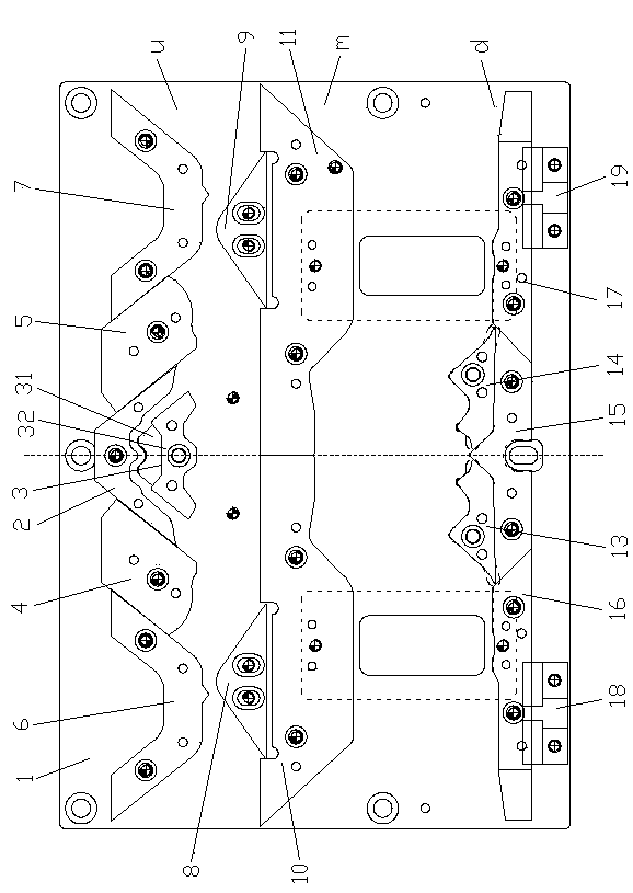
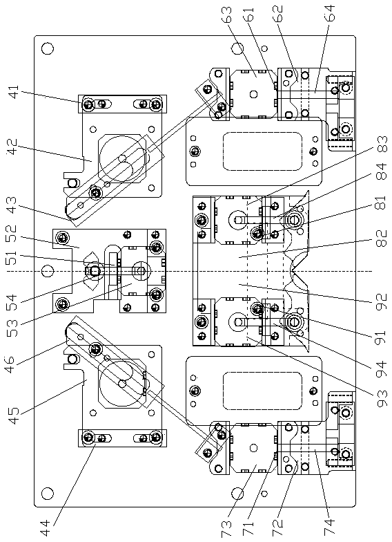
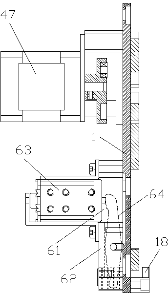
[0042] see Figure 1 to Figure 15 , the bottom plate of the computerized knitting machine with a controllable homing structure in this embodiment includes a bottom plate body 1, a herringbone triangle 2, a transfer triangle 3, a left stitch triangle 4, a right stitch triangle 5, and a left knitting upper homing triangle 6 , Right knitting upper homing cam 7, left knitting lower homing cam 8, right knitting lower homing cam 9, left needle selection upper homing cam 10, right needle selection upper homing cam 11, left needle starting cam 13, right Needle starting cam 14, middle homing cam 15, left needle selection lower homing cam 16, right needle selection lower homing cam 17, left homing cam 18, r...


PUM


Abstract

The utility model relates to a bottom plate with a controllable return position structure for a computerized knitting machine. The bottom plate has the characteristics of simple structure, reasonable design, reliable performance, long service life and low abrasion, and comprises a bottom plate body, an inverted r-shaped triangular plate, a needle turning triangular plate, a left knitting upper return position triangular plate, a right knitting upper return position triangular plate, a left knitting lower return position triangular plate, a right knitting lower return position triangular plate, a left needle selection upper return position triangular plate, a right needle selection upper return position triangular plate, a left casting-on triangular plate, a right casting-on triangular plate, a left needle selection lower return position triangular plate, a right needle selection lower return position triangular plate, a left return position triangular plate and a right return position triangular plate, wherein the inverted r-shaped triangular plate, the needle turning triangular plate, the left knitting upper return position triangular plate and the right knitting upper return position triangular plate are mounted at the upper part of the bottom plate body; the left knitting lower return position triangular plate, the right knitting lower return position triangular plate, the left needle selection upper return position triangular plate and the right needle selection upper return position triangular plate are mounted in the middle of the bottom plate body; and the left casting-on triangular plate, the right casting-on triangular plate, the left needle selection lower return position triangular plate, the right needle selection lower return position triangular plate, the left return position triangular plate and the right return position triangular plate are mounted at the lower part of the bottom plate body. The bottom plate is characterized by further comprising a left return position controller and a right return position controller which are movably connected to the bottom plate body through a left return position controller and a right return position controller respectively. The bottom plate has the advantages of reasonable structural design, reliable performance, long service life, low noise during the working process and low abrasion.

Description

technical field [0001] The invention relates to a bottom plate of a computerized knitting machine, in particular to a bottom plate of a computerized knitting machine with a controllable homing structure, which belongs to a core component of the computerized knitting machine. Background technique [0002] The bottom plate of the computerized knitting machine belongs to a core component of the computerized knitting machine. The structure design of the existing bottom plate used in the computerized knitting machine is not reasonable enough, and the performance is not reliable enough, thereby reducing the overall performance of the computerized knitting machine. The existing computerized knitting machine base plates are equipped with a left homing cam and a right homing cam, and the left homing cam and the right homing cam are fixed on the base body and cannot be moved. When the computerized knitting machine is running At this time, all the stitches are lifted to the needle sele...

Claims


Application Information

Patent Timeline
Patent Type & Authority Patents(China)
IPC IPC(8): D04B15/32
Inventor 王靖敏
Owner 桐乡市强隆机械有限公司
Why Eureka
Try Eureka