Tie-back self-lock mechanism for suspended packer

A hanging packer and self-locking technology, applied in wellbore/well components, earth-moving drilling, etc., can solve the problems of unsealed pipe string, failure of seal between anchor claw and body, and failure of pipe string to be raised, and achieve reliable sealing. Effect

Active Publication Date: 2012-05-09
BC P INC CHINA NAT PETROLEUM CORP +1
View PDF6 Cites 8 Cited by
  • Summary
  • Abstract
  • Description
  • Claims
  • Application Information

AI Technical Summary

Problems solved by technology

[0005] However, the prior art represented by the above-mentioned patent documents still has the following deficiencies: after the hydraulic anchor has been working in the well for a long time, due to reasons such as corrosion, scaling, and sand settling, on the one hand, the anchor fluke may not be easily

Method used


Image

  • Tie-back self-lock mechanism for suspended packer
  • Tie-back self-lock mechanism for suspended packer
  • Tie-back self-lock mechanism for suspended packer

Examples


Embodiment 1

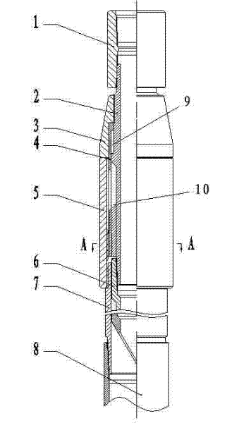
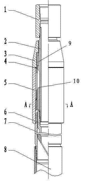
[0025] The invention discloses a tie-back self-locking mechanism for a suspended packer, which comprises a tie-back device and a self-locking device. tube; the self-locking device includes an undercut connector, a tie-back barrel and a lower joint; the upper joint, the central tube, the claw limit sleeve and the tie-back intubation are threaded from top to bottom, and the The above-described undercut connector, return barrel and lower joint are connected by threads from top to bottom, the lower end of the claw is provided with a trapezoidal male thread, and the lower end of the undercut connector is provided with a trapezoidal female thread that matches the claw. The spring claw slides axially up and down in the chute formed between the central tube and the spring claw limiting sleeve, the return sleeve is located under the undercut connector, and the return inserting tube is located under the spring claw.

Embodiment approach

[0027] The best implementation mode of the present invention is as follows:

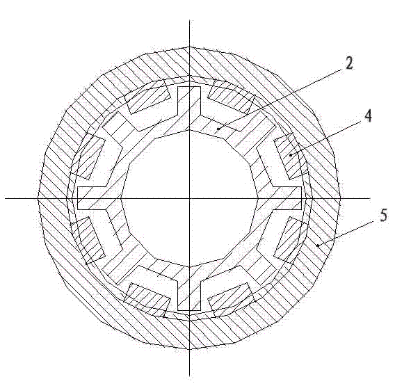
[0028] The structure and connection relationship of the present invention: the present invention includes a tie-back device and a self-locking device. The tie-back device is composed of an upper joint 1, a central tube 2, a claw limit sleeve 3, a claw 4, and a tie-back intubation tube 6. The lock device is composed of an undercut connector 5, a return barrel 7 and a lower joint 8; the lower end of the claw 4 has a trapezoidal male button thread, the lower end of the undercut connector 5 has a trapezoidal female button thread matching the claw 4, and the claw 4 It can slide up and down in the axial direction in the chute formed by the center tube 2 and the claw limit sleeve 3. The lower end of the center tube 2 is evenly distributed with an axial limit shoulder, which limits the claw 4 from rotating in the circumferential direction and can only rotate along the Sliding in the axial direction; there is...


PUM


Abstract

The invention discloses a tie-back self-lock mechanism for a suspended packer, which comprises a tie-back device and a self-locking device. The tie-back device comprises an upper connector, a central pipe, an elastic claw limit sleeve, an elastic claw and a tie-back inserting pipe. The self-lock device comprises a back-off connector, a tie-back barrel and a lower connector. The upper connector, the central pipe, the elastic claw limit sleeve and the tie-back inserting pipe are in threaded connection from up to down. The back-off connector, the tie-back barrel and the lower connector are in threaded connection from up to down. A ladder-shaped male buckle thread is arranged at the lower end of the elastic claw, a ladder-shaped female buckle thread matched with the elastic is arranged at the lower end of the back-off connector, the elastic claw moves up and down in the axial direction in a slide groove formed between the central pipe and the elastic claw limit sleeve, the tie-back barrel is positioned under the back-off connector, and the tie-back inserting pipe is positioned below the elastic claw. The tie-back self-lock mechanism can substitute tubular columns needing waterpower anchors to enable the tubular columns to be reliable in sealing, can pull out tie-back oil pipe strings at any time, and avoids accidents of oil-gas well engineering.

Description

[0001] technical field [0002] The invention relates to the technical field of downhole tool manufacturing for oil and gas well fracturing and acidification production stimulation reconstruction, in particular to a tieback self-locking mechanism for a suspension packer used for downhole fracturing and acidification construction of oil and gas wells and well completion and production of oil and gas production. Background technique [0003] Before open-hole staged fracturing and acidizing in horizontal wells, it is necessary to send tool strings such as suspension packers, open-hole packers, ball-pitching sleeves, and differential pressure sleeves into the downhole design depth for setting and suspension through the drill pipe, and then take them out. Feed into the drilling tool, lower the tie-back cannula and tubing string, and tie-back to the tie-back barrel at the upper end of the hanging packer, so as to facilitate subsequent fracturing and acidizing construction and p...

Claims


Application Information

Patent Timeline
IPC IPC(8): E21B23/00
Inventor 张道鹏张毅超潘勇周正叶登胜
Owner BC P INC CHINA NAT PETROLEUM CORP
Why Eureka
Try Eureka