
Fully mechanized mining face hydraulic support beam-type retracting device

A technology of fully mechanized mining face and hydraulic support, applied in mine roof support, mining equipment, earthwork drilling and other directions, can solve the problems of shortening the auxiliary time of hydraulic support relocation of fully mechanized mining face, high labor intensity, slow retraction speed, etc. , to achieve the effect of improving the speed of retracting, relocating and reversing the support of the fully mechanized mining face, improving high production and efficiency, safety, stability and reliability.

Active Publication Date: 2012-05-09
TAIYUAN INST OF CHINA COAL TECH & ENG GROUP +1
View PDF6 Cites 22 Cited by
  • Summary
  • Abstract
  • Description
  • Claims
  • Application Information

AI Technical Summary

Problems solved by technology

[0003] In order to solve the problem that the hydraulic support of the existing fully mechanized mining face is withdrawn mostly by winch and wire rope traction, there are problems such as large safety hazards, high labor intensity, and slow retraction speed, and the like, a hydraulic support beam type hydraulic support of the fully mechanized mining face is provided. Retraction device shortens the relocation assistance time of the hydraulic support in the fully mechanized mining face

Method used


Image

  • Fully mechanized mining face hydraulic support beam-type retracting device
  • Fully mechanized mining face hydraulic support beam-type retracting device
  • Fully mechanized mining face hydraulic support beam-type retracting device

Examples


Embodiment Construction

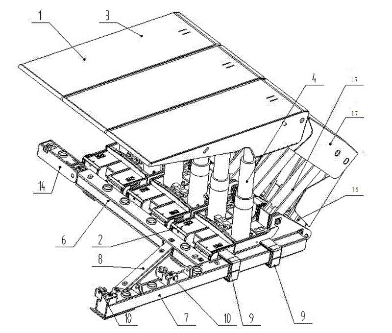
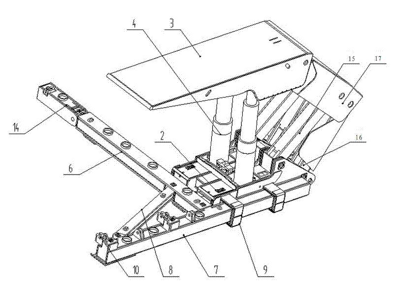
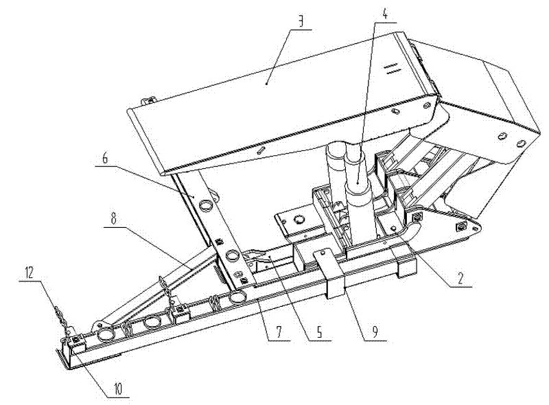
[0016] The hydraulic support beam type retraction device of the fully mechanized mining face, such as figure 1 As shown, it includes at least three retraction shielding brackets arranged side by side. The retraction shielding bracket 1 includes a base 2, a front connecting rod 15, a rear connecting rod 16, a shielding beam 17, and a top beam 3. Between the base and the top beam It is connected with a column 4, and a push rod 5 and a push cylinder are arranged through the base, and a two-way lock is arranged in the hydraulic control system of the push cylinder. Well known, one end of the push rod is hinged with the end of the piston rod of the push cylinder, such as figure 2 , 3 As shown, the beam type retraction device also includes a crossbeam 6 located in front of each retraction shield support base 2, a longitudinal beam 7 positioned outside the side retraction shield support 18, and a diagonal brace connected between the crossbeam and the longitudinal beam. Rigid triang...


PUM


Abstract

The invention relates to a coalmine fully mechanized mining complete equipment retracting device and particularly relates to a fully mechanized mining face hydraulic support beam-type retracting device which can be used for solving the problems such as high potential safety hazard, high labor intensity, slow retracting speed and the like caused by the adoption of a winch and a steel wire rope for traction in the prior art. The device comprises at least three retracting shield supports, wherein each retracting shield support comprises a base, a front connecting rod, a rear connecting rod, a shield beam, a top beam and an upright, and a push rod and a push oil cylinder are arranged in each base; the device also comprises a rigid triangular beam-type retracting device composed of a cross beam, a longitudinal beam and an inclined breast beam; a guide sleeve is arranged at the outer side of the base of the lateral retracting shield support; the longitudinal beam is arranged in the guide sleeve in a penetrating manner and is provided with a chain adjuster, and the chain adjuster is provided with a chain; and the power output end of the push rod of each retracting shield support is hinged with the cross beam. By utilizing the device, a support to be retracted can be retracted through self movement, the speed of retracting and moving a fully mechanized mining face support to a working face is improved, the labor intensity of workers is alleviated, the production efficiency is improved, the coalmine production safety is enhanced, and the high yield and high efficiency of a fully mechanized working face are improved.

Description

technical field [0001] The invention relates to a retracting device for a complete set of fully mechanized mining equipment in a coal mine, in particular to a hydraulic support beam type retracting device for a fully mechanized mining face. Background technique [0002] Coal mine fully mechanized mining hydraulic support is an important equipment in the complete set of coal mine fully mechanized mining equipment. The withdrawal of fully mechanized mining hydraulic supports is the most intensive task in the withdrawal of fully mechanized mining equipment. Because there are fallen coal gangue and rocks accumulated behind the hydraulic supports, it belongs to the regional geology where the pressure is concentrated. The conditions are harsh. At present, the hydraulic support of the fully mechanized mining face is pulled back by the winch and the wire rope. Since the wire rope is easy to break and fly, there is a great potential safety hazard. In addition, the labor intensity is ...

Claims


Application Information

Patent Timeline
IPC IPC(8): E21D23/16
Inventor 宋德军李刚闫殿华桑盛远曹俊锁周凯赵帅赵建武康富军李彬彬宋涛李莉马平辉王本林王军郭猛郭振兴刘玉波韩俊效张学瑞
Owner TAIYUAN INST OF CHINA COAL TECH & ENG GROUP
Features
  • Generate Ideas
  • Intellectual Property
  • Life Sciences
  • Materials
  • Tech Scout
  • Unparalleled Data Quality
  • Higher Quality Content
  • 60% Fewer Hallucinations
Learn More