Control device for handrail drive device

A driving device and control device technology, used in escalators, transportation and packaging, etc., can solve the problems of shortened parts life, deteriorated driving performance, and increased traction slippage, etc., to extend the life of parts, improve maintenance operations, and reduce driving performance. Degraded effect

Inactive Publication Date: 2012-05-09
MITSUBISHI ELECTRIC CORP
View PDF5 Cites 6 Cited by
  • Summary
  • Abstract
  • Description
  • Claims
  • Application Information

AI Technical Summary

Problems solved by technology

Therefore, only by detecting the speed of the steps and the speed of the handrail, it is impossible to isolate the main cause of the slipping of the speed change of the handrail. Abrasion damage of the handrail and handrail, due to the shortened life of the parts of the roller and the handrail and the deterioration of the driving performance due to wear, maintenance operations to improve the driving performance become frequent

Method used


Image

  • Control device for handrail drive device
  • Control device for handrail drive device
  • Control device for handrail drive device

Examples


Embodiment approach 1

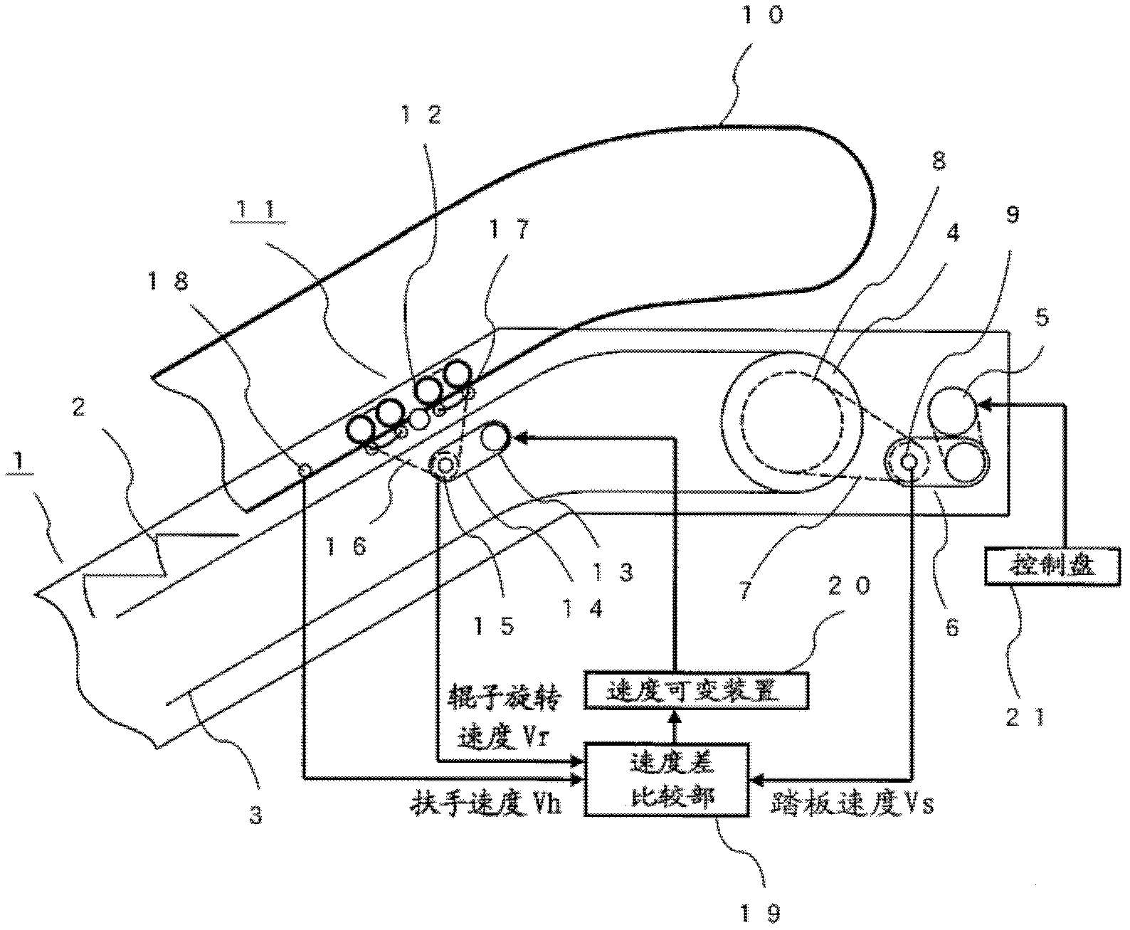
[0019] figure 1 It is a figure which shows the structure of the control apparatus of the handrail drive apparatus concerning Embodiment 1 of this invention. exist figure 1 Among them, the pedals 2 of the passenger conveyor 1 are connected to a pedal chain 3 . Power of a pedal driving machine constituted by a pedal motor 5 and a pedal reducer 6 installed on the upper portion of the passenger conveyor 1 is transmitted to the pedal chain 3 via a chain 7 , a sprocket 8 and a sprocket 4 . The handrail 10 transmits the power of the handrail driving machine constituted by the handrail motor 13 and the handrail reducer 14 to each roller 12 via the chain 16, and the handrail 10 is clamped by the rollers 12 and the pressing rollers 17, thereby driving the handrail 10. In addition, reference numeral 11 denotes a handrail driving device.

[0020] The driving speed of the pedal 2 is performed by inputting a desired speed command from the control panel 21 to the pedal driving machine. R...

Embodiment approach 2

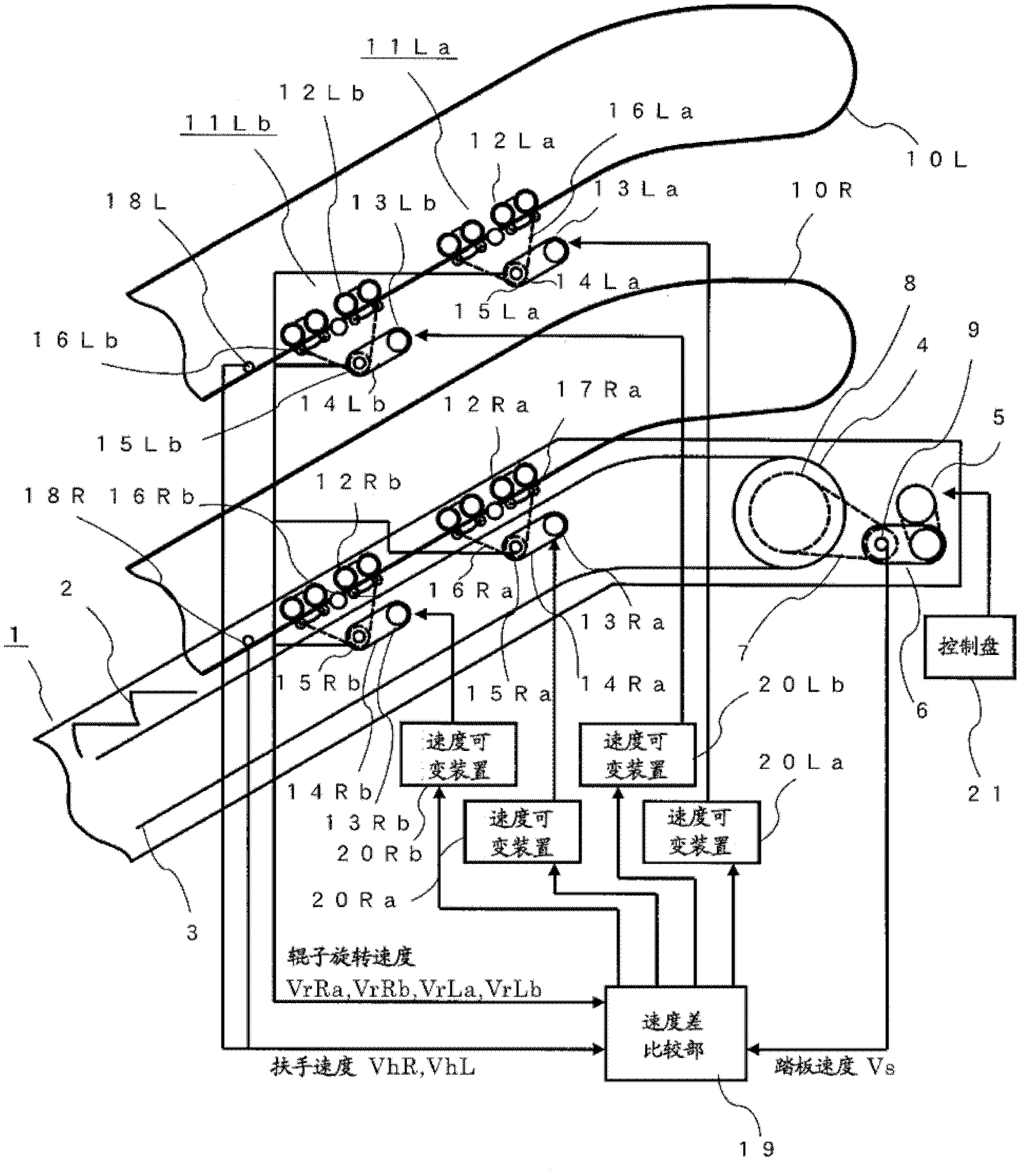
[0031] image 3 It is a figure which shows the structure of the control apparatus of the handrail drive apparatus concerning Embodiment 2 of this invention. exist image 3 Among them, the pedals 2 of the passenger conveyor 1 are connected to a pedal chain 3 . Power of a pedal driving machine constituted by a pedal motor 5 and a pedal reducer 6 installed on the upper portion of the passenger conveyor 1 is transmitted to the pedal chain 3 via a chain 7 , a sprocket 8 and a sprocket 4 .

[0032]The right (left) handrail 10R (10L) is composed of the right (left) handrail motors 13Ra, 13Rb (13La, 13Lb) and the handrail speed reducers 14Ra, 14Rb (14La, 14Lb), which are arranged separately on the left and right sides. The power of the driver for the handrail is transmitted to the rollers 12Ra, 12Rb (12La, 12Lb) via the chains 16Ra, 16Rb (16La, 16Lb), and the rollers 12Ra, 12Rb (12La, 12Lb) and the push rollers 17Ra, 17Rb (17La, 17Lb) ) pinches the armrest 10R (10L), thereby drivin...

Embodiment approach 3

[0046] Figure 5 It is a figure which shows the structure of the control apparatus of the handrail drive apparatus concerning Embodiment 3 of this invention. exist Figure 5 In this example, the pedals 2 of the passenger conveyor 1 are connected to a pedal chain 3 . Power of a pedal driving machine constituted by a pedal motor 5 and a pedal reducer 6 installed on the upper portion of the passenger conveyor 1 is transmitted to the pedal chain 3 via a chain 7 , a sprocket 8 and a sprocket 4 . The right (left) handrail 10R (10L) is composed of the right (left) handrail motors 13Ra, 13Rb (13La, 13Lb) and the handrail speed reducers 14Ra, 14Rb (14La, 14Lb), which are arranged separately on the left and right sides. The power of the driver for the handrail is transmitted to the rollers 12Ra, 12Rb (12La, 12Lb) via the chains 16Ra, 16Rb (16La, 16Lb), and the rollers 12Ra, 12Rb (12La, 12Lb) and the push rollers 17Ra, 17Rb (17La, 17Lb) ) pinches the armrest 10R (10L), thereby driving...


PUM


Abstract

Provided is a control device for a handrail drive device, configured to match a step speed and a handrail speed to each other while minimizing damage to equipment of a traction drive unit. A control device for a handrail drive device, comprising: a step speed detector (9); a handrail speed detector (18); a roller rotational speed detector (15); a speed difference comparison unit (19) for generating a speed command value for the drive unit of the handrail drive device (11) on the basis of the difference between a step speed and a handrail speed and of the difference between a roller rotational speed and the handrail speed; and a speed change device (20) for driving the electric motor of the handrail drive device (11) depending on the speed command value from the speed difference comparison unit (19). When the difference between the step speed and the handrail speed is within the range of a set value and the difference between the handrail speed and the roller rotational speed is within the range of a set value, the control device generates a handrail speed command value obtained by correcting the difference between the handrail speed and the roller rotational speed with reference to the step speed.

Description

technical field [0001] The present invention relates to a control device of a handrail driving device of a passenger conveying equipment in which a driving machine for driving a pedal and a driving machine for driving a handrail are provided separately. Background technique [0002] As a conventional driving device for passenger conveying equipment, there is a device that includes a step speed detector that detects the speed of the steps and a handrail speed detector that detects the speed of the handrail. If the value of the step speed detector and the value of the handrail speed detector If the deviation is within the specified range, the handrail is driven by the handrail speed command to correct the deviation, so that the speed of the step and the handrail are consistent. On the contrary, if the deviation between the value of the step speed detector and the value of the handrail speed detector is within the specified range Above, the step and the handrail are stopped, th...

Claims


Application Information

Patent Timeline
Patent Type & Authority Applications(China)
IPC IPC(8): B66B23/04
CPCB66B23/04
Inventor 长冈孝彦宫崎嘉寿也
Owner MITSUBISHI ELECTRIC CORP
Why Eureka
Try Eureka