Axial angular contact rolling bearing, in particular for the support of a round table at a machine tool, and method for assembling such an axial angular contact rolling bearing
What is AI technical title?
AI technical title is built by PatSnap AI team. It summarizes the technical point description of the patent document.
A rolling bearing and angular contact technology, which is applied in the direction of rolling contact bearings, bearing assembly, shafts and bearings, etc., can solve problems such as high cost and complexity, and achieve the effects of low assembly cost, high raceway load capacity, and low manufacturing cost
Inactive Publication Date: 2015-08-19
SCHAEFFLER TECH AG & CO KG
View PDF9 Cites 0 Cited by
Summary
Abstract
Description
Claims
Application Information
AI Technical Summary
This helps you quickly interpret patents by identifying the three key elements:
Problems solved by technology
Method used
Benefits of technology
Problems solved by technology
Because the necessary offset of the two raceway pitches via the inner and outer rings and the introduction of the bearing preload by using different ball classifications is relatively complex, although there is a one-piece embodiment of the two bearing rings , such axial angular contact ball bearings are still extremely costly overall
Method used
Image
Click on the blue label to locate the original text in one second.
Reading with bidirectional positioning of images and text.
Examples
Embodiment Construction
[0045] Detailed description of the drawings
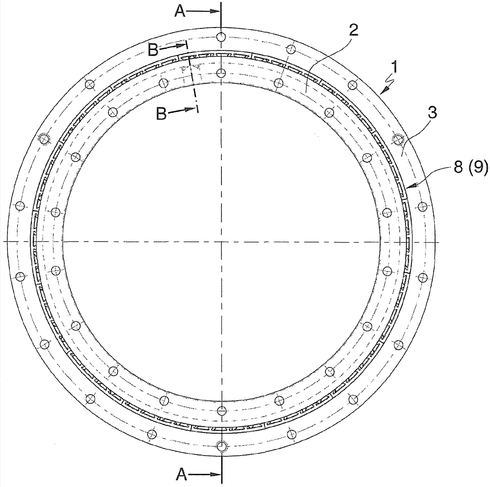
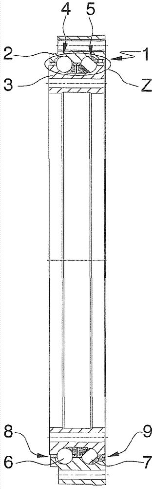
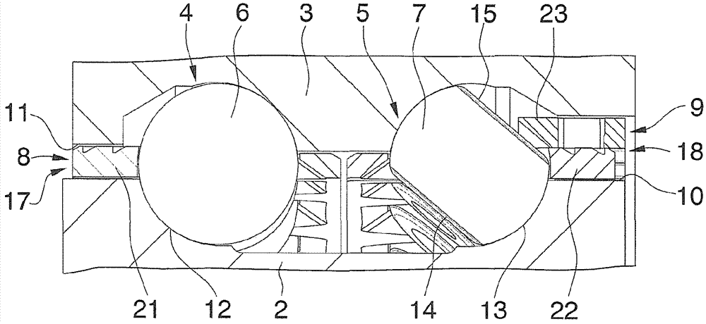
[0046] Depend on figure 1 and figure 2 An axial angular contact rolling bearing 1 suitable for the support of a round table on a machine tool, which essentially consists of a one-piece inner bearing ring 2 and a one-piece outer The bearing ring 3 consists of a plurality of rolling elements 6, 7 arranged side by side in two rows 4, 5 between the bearing rings 2, 3, the rolling elements 6, 7 are connected to each other in the circumferential direction by two bearing cages 8, 9 Keep evenly spaced. available here at image 3 It can be seen that the two rows 4 , 5 of the rolling elements 6 , 7 are placed opposite each other in an O-arrangement and, at a defined pressure angle, with their running surfaces on the two inner bearing rings 2 arranged side by side Rolls on raceways 12, 13 at the outer side 10 of the outer bearing ring 3 and at the inner side 11 of the outer bearing ring 3. In addition, in figure 1 and 2 The bores in t...
PUM
Abstract
The invention relates to an axial angular-contact rolling bearing (1) which is composed substantially of a single-piece inner bearing ring (2) and of a single-piece outer bearing ring (3) and of a multiplicity of rolling bodies (6, 7) which are arranged adjacent to one another in at least two rows (4, 5) between the bearing rings (2, 3) and which are held at uniform intervals to one another in the circumferential direction by at least two bearing cages (8, 9) and which roll under defined contact angles with their running surfaces on at least two raceways (12, 13) arranged next to each other on the outer side (10) of the inner bearing ring (2) and on the inner side (11) of the outer bearing ring (3). According to the invention, one of the at least two rows (4, 5) of the rolling bodies (6, 7) is formed by bearing balls, while the other of the at least two rows (4, 5) of the rolling bodies (6, 7) is composed of spherical rollers, each having two side surfaces (14, 15) flattened symmetrically proceeding from a spherical basic shape, wherein the inner bearing ring (2) has a single radial filling bore (16) arranged axially eccentrically adjacent to one of the two raceways (12, 13), through which radial filling bore (16) all of the rolling bodies (6, 7) of the at least two rows (4, 5) can be filled into their raceways (12, 13), and wherein the respective bearing cages (8, 9) of the at least two rows (4, 5) of the rolling bodies (6, 7) are formed as segmented cages composed of a plurality of juxtaposed identical cage segments (17, 18). The invention also relates to a method for assembling an axial angular-contact rolling bearing (1) designed according to the invention.
Description
technical field field of invention [0001] The invention relates to an axial angular contact rolling bearing and a method for assembling such an axial angular contact rolling bearing, and the invention can be used particularly advantageously at the bearing of a circular table of a machine tool. Background technique Background of the invention [0002] Modern round table bearings for machine tools are currently manufactured as mounted precision bearings for combined loads with high demands on running accuracy and are designed either as axial radial bearings, depending on the rotational speed and engagement duration, Either configured as an axial angular contact ball bearing. Both bearing embodiments absorb radial loads and axial loads on both sides as well as tilting moments and are preloaded without play in the radial and axial directions. Axial radial bearings are mainly used in standard applications with low rotational speeds and short engagement periods and are genera...
Claims
Application Information
Patent Timeline
Application Date:The date an application was filed.
Publication Date:The date a patent or application was officially published.
First Publication Date:The earliest publication date of a patent with the same application number.
Issue Date:Publication date of the patent grant document.
PCT Entry Date:The Entry date of PCT National Phase.
Estimated Expiry Date:The statutory expiry date of a patent right according to the Patent Law, and it is the longest term of protection that the patent right can achieve without the termination of the patent right due to other reasons(Term extension factor has been taken into account ).
Invalid Date:Actual expiry date is based on effective date or publication date of legal transaction data of invalid patent.

