

Machine tool for the machining of workpieces
A technology for machining workpieces and workpieces, applied in the field of machine tools for machining workpieces, can solve problems such as inability to realize workpiece cutting and separation of parts, and achieve the effects of rapid removal and improved process reliability.
- Summary
- Abstract
- Description
- Claims
- Application Information
AI Technical Summary
Problems solved by technology
Method used
Image

Examples
Embodiment Construction
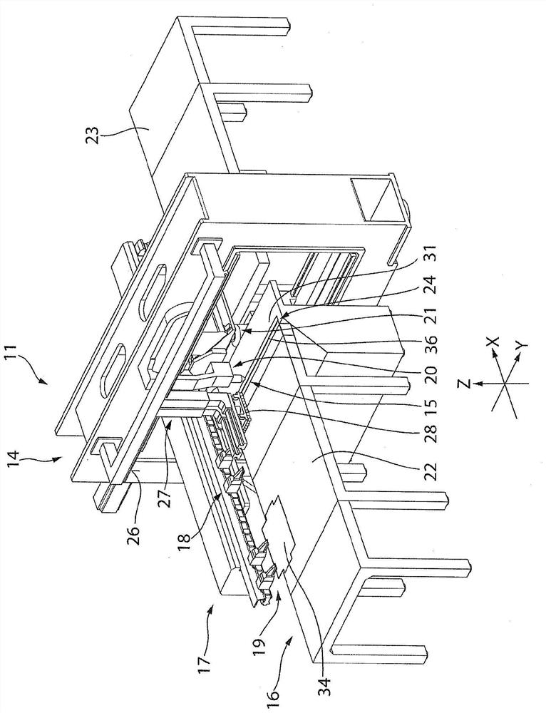
[0036] exist figure 1 The processing machine 11 is represented three-dimensionally in the middle. The processing machine 11 is, for example, a mixing processing machine. The hybrid processing machine 11 enables both laser processing and stamping processing of plate-shaped workpieces. Alternatively, the processing machine 11 can also be a laser cutting processing machine only. The processing machine 11 has a closed base body 14 , in particular a surrounding frame, which preferably extends in the Y direction. A workpiece carrier 16 extending in the X direction traverses the frame 14 . The workpiece carrier 16 is equipped with a holding device 17 with holding elements 18 , 19 . The holding elements 18 , 19 are preferably designed as clips or jaws. The trimmed workpiece 34 , which is preferably designed as a plate-shaped workpiece, can be held by the holding elements 18 , 19 and moved, for example, in the X direction of the workpiece plane (X / Y plane). To process the plate-s...
PUM
 Abstract
Description
Claims
Application Information