Pipe fitting for absorbing expansion and earthquake-proof

A pipe joint and shock-resistant technology, applied in the field of pipe joints, can solve the problems of interfering with fluid flow, hindering the smooth flow of fluid, expensive production costs, etc. The effect of shock resistance

Active Publication Date: 2012-05-16
李到妍 +1
View PDF6 Cites 2 Cited by
  • Summary
  • Abstract
  • Description
  • Claims
  • Application Information

AI Technical Summary

Problems solved by technology

[0025] However, as the outer diameter and inner diameter decrease, at one end of the tube 21 having a certain length, the flow pressure of the fluid inside the flow tube 21 rises to a level corresponding to the decrease in the inner diameter, which not only interferes with the flow of the fluid, but also hinders the flow of the fluid. smooth flow of fluid
[0026] In addition, when the stopper 21b installed to limit the sliding range of the tube 21 is damaged due to the excessive sliding of the tube 21, the combination of the tube 21, the spherical tube 22 and the housing 23 will be released, so that the original pipe joint 20 cannot be completed. function of
[0027] In addition, since the fluid flows into the space formed between the outer periphery of the pipe 21 and the curved surface of the inner periphery of the spherical pipe 22, the flow of the fluid cannot be completed smoothly due to the flow pressure generated when the fluid flows in and out and the vortex phenomenon of the fluid, etc.
[0028] In addition, although the pipe joint 20 has the function of shock resistance, it has limitations in installation due to its high manufacturing cost, and because of its complicated manufacturing structure, it brings many difficulties to the manufacture of the pipe joint 20.

Method used


Image

  • Pipe fitting for absorbing expansion and earthquake-proof
  • Pipe fitting for absorbing expansion and earthquake-proof
  • Pipe fitting for absorbing expansion and earthquake-proof

Examples


Embodiment Construction

[0069] Hereinafter, the telescopic and earthquake-resistant pipe joint according to the present invention will be described in detail with reference to the drawings.

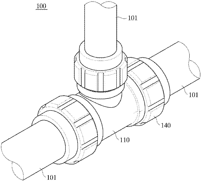
[0070] image 3 is a schematic perspective view showing a telescopic and shockproof pipe joint according to the present invention, Figure 4 is in image 3 An isolated perspective view of the fitting shown in, Figure 5a and Figure 5b is in image 3 The side sectional view and the use state diagram of the pipe joint shown in Figure 6a and Figure 6b is shown in Figure 4 A side sectional view of the cap and pressurized parts shown in .

[0071] First, if Figure 3 to Figure 4 As shown in the figure, the flexible and shockproof pipe joint 100 according to the present invention includes:

[0072] A tube body 110, which can be inserted into one end of a plurality of tubes 101, and a receiving hook 111 is formed on the inner periphery of the end of the inserted tube 101 to expand the inner diameter;

[0...


PUM


Abstract

An anti-expansion and anti-seismic pipe fitting. The pipe fitting includes a body into which end portions of plural pipes are inserted. The body has a receiving jaw formed on the inner circumferential surface of an end portion, into which each of the pipe is inserted such that an inner diameter of the body is enlarged. A packing is arranged on the receiving jaw. A cap is coupled to the end portion of the body such that the packing and the pressurizing member are mounted inside the cap. Buffering means are included for absorbing expansion and contraction of the pipe. The pipe fitting can absorb deformation due to the expansion or contraction of the pipes. Moreover, because all of the pipes and the pipe fitting have the same inner diameter, the fluid flowing inside the pipes maintains uniform pressure, and hence, the fluid can flow smoothly inside the pipes.

Description

technical field [0001] The present invention relates to a pipe joint, in particular to a pipe joint for expansion and shock resistance manufactured to connect a plurality of pipes to each other, seal them from the outside, and absorb the expansion and contraction deformation of the pipes due to internal and external heat and environment. Background technique [0002] Usually, when fluids such as liquids and gases are continuously transported over long distances, tubes are often used as the transport tool. [0003] These tubes are often made of various materials, such as plastics or metals, depending on the type, composition, and use environment of the fluid. [0004] These pipes, from the point of supply all the way to the point of consumption, are connected to each other by a plurality of pipes, and the connection points of these pipes are generally equipped with pipe joints. [0005] Here, when a liquid or gas with a large temperature change flows in the pipe, or the pipe...

Claims


Application Information

Patent Timeline
Patent Type & Authority Applications(China)
IPC IPC(8): F16L27/12
CPCF16L27/1008F16L19/0218F16L19/0286F16L27/12
Inventor 李到妍宋炫雄
Owner 李到妍
Why Eureka
Try Eureka