
Projector

A technology for projectors and images, which is applied in the field of projectors, can solve the problems of reducing the light intensity of the surface beam, light loss, and increasing the cost of use, and achieves reduced light dissipation loss, uniform light intensity distribution, and good light uniformity Effect

Inactive Publication Date: 2012-05-16
SHENZHEN TONGFAXIN CIRCUIT TECH
View PDF9 Cites 3 Cited by
  • Summary
  • Abstract
  • Description
  • Claims
  • Application Information

AI Technical Summary

Problems solved by technology

[0005] In the light source lens group mentioned above, when the uniform light treatment is performed in the process of sorting the light beam, since the light incident surface of the uniform light lens is an uneven surface, when the light enters the uniform light lens, the incident angles of each point are different, and each point enters the uniform light. The angle of refraction is also different when the light of the optical lens exits the light, so some light will escape out of the irradiation area of ​​the image imaging device and cause light loss, reduce the light intensity of the surface beam formed, make the projected image darker, and be vulnerable to the projection environment. Interference from other light sources affects the use of the projector
In order to increase the light intensity of the surface beam, it is generally used to increase the power of the light source module, which will increase the energy consumption, increase the cost of use, and increase the difficulty of heat dissipation of the light source module, and the service life of the image; another method is It is to increase the light converging rate of the light converging mirror to make the intensity of the formed high-brightness beam more concentrated, but this method will increase the difficulty of uniform light treatment, so that the surface beam formed by the uniform light lens will still have a center The phenomenon that the brightness of the area is higher than that of the surrounding area, which reduces the clarity of the projected image
[0006] Therefore, it is difficult for existing projectors to take into account the two aspects of reducing light loss and improving illumination uniformity.

Method used


Image

  • Projector
  • Projector
  • Projector

Examples


Embodiment Construction

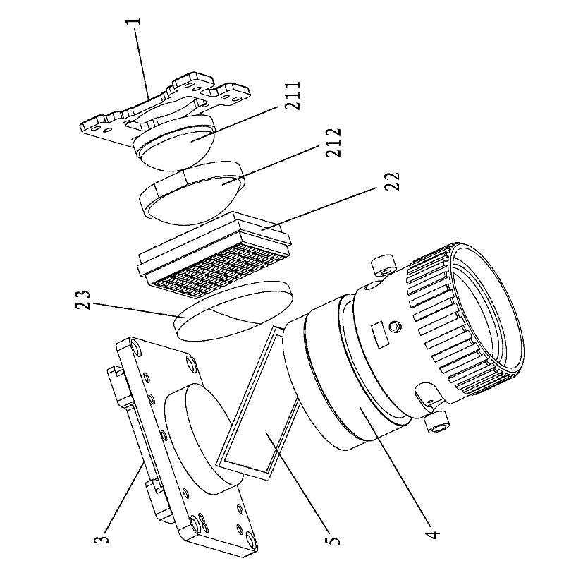
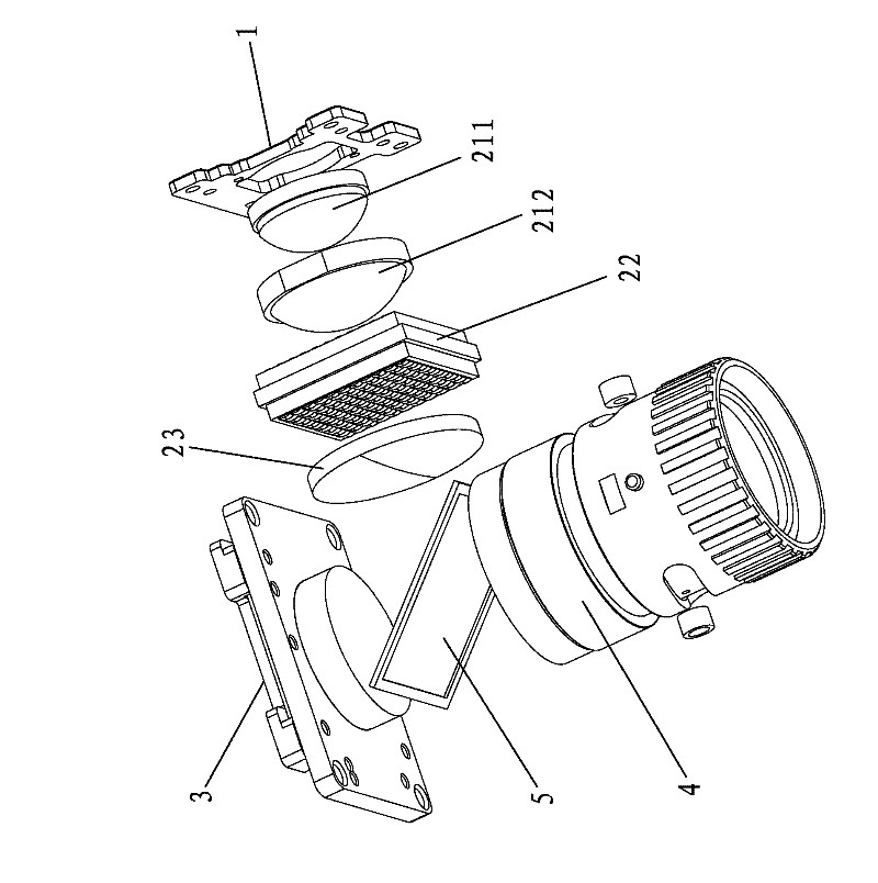
[0030] The present invention will be further described below in conjunction with the accompanying drawings and embodiments.

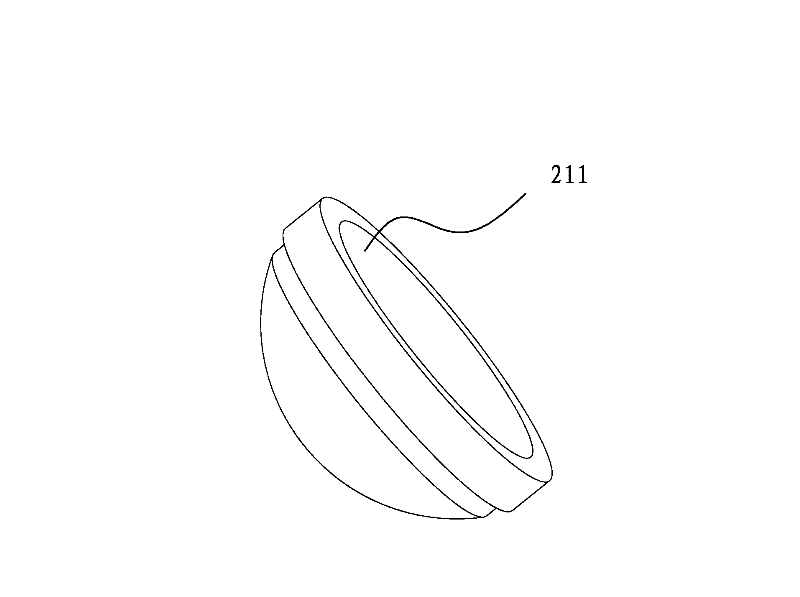
[0031] See figure 1 with figure 2 As shown, the projector according to the present invention includes a light source module 1, a light source lens group, an imaging device 3 and a projection lens group 4. The light source module 1 includes a light source formed by a plurality of point light source arrays, so The light source lens group has a light converging mirror and a uniform light lens 22, and the light incident surface and the light output surface of the light uniform lens 22 are evenly arrayed with a plurality of convex points 221; the light source lens group is provided with a filter at the light output end A converging mirror 23, the light incident surface of the filter converging mirror 23 is a convex arc surface.

[0032] When the present invention is in use, after the light is emitted from the light source module 1, it is collected by the ...


PUM


Abstract

The invention discloses a projector comprising a light source module, a light source lens group, an imaging device and a projection lens group. An out-light surface and an in-light surface of a uniform light lens both are provided with a plurality of salient points in array form; the light source lens group is provided with a filtering converging lens at an out-light end, and the in-light surface of the filtering converging lens is an outward convex arc-shaped surface; the out-light surface of the uniform light lens is provided with the salient points, and the light equalization effect is good, so, even if the light converging rate of the filtering converging lens is high, a surface beam with uniform light intensity distribution also can be formed; with the filtering converging lens, light effusion loss is reduced, and the light beam, which still has non-uniform light intensity after being processed in light equalization treatment by the light uniform lens, can have more uniform light intensity distribution after being further processed in the light equalization treatment by the filtering converging lens. The projector reduces optical loss in the light source settling process, and improves illumination uniformity in an illumination area, so that the projected images are clear and brighter, and the projector is affected less by environment light source and has good service performance.

Description

technical field [0001] The invention relates to the field of image output equipment, in particular to a projector. Background technique [0002] A projector generally includes a light source module, a light source lens group, an image imaging device, and a projection lens group. During operation, the light beam emitted from the light source module is organized into a uniform beam through the light source lens group. The uniform beam is projected on the image imaging device to illuminate the formed After the image of the imaging device is amplified and output by the projection lens group, a projected image is formed in front of the projection lens group. [0003] The clarity and brightness of the projected image depend on the light intensity and illumination uniformity of the uniform light beam supplied to the imaging device, and the light intensity and illumination uniformity of the uniform light beam are completed by the light source lens group to organize the light beam em...

Claims


Application Information

Patent Timeline
Patent Type & Authority Applications(China)
IPC IPC(8): G03B21/20G02B27/18F21V13/00
Inventor 王心范
Owner SHENZHEN TONGFAXIN CIRCUIT TECH
Learn More