
Infrared touch device and method

An infrared touch and touch screen technology, applied in the direction of instruments, electrical digital data processing, data processing input/output process, etc., can solve the problems of uneconomical, slow response speed, increased cost, etc., to improve scanning speed, reduce cost, Fast response to touch

Active Publication Date: 2014-07-23
HUAWEI TEHCHNOLOGIES CO LTD
View PDF7 Cites 0 Cited by
  • Summary
  • Abstract
  • Description
  • Claims
  • Application Information

AI Technical Summary

Problems solved by technology

But the disadvantage of this is that only one pair of infrared emitting elements and infrared receiving elements are working at a time. Such an infrared touch device responds slowly, and the user's touch experience is not good.
In the prior art, multiple sets of infrared emitting modules and infrared receiving module groups are used on the touch device, and each infrared emitting module and infrared receiving module group is controlled by a separate control chip, so that the touch device can be activated at the same time. Multiple groups of infrared emitting elements and infrared receiving elements are working, but this method increases the cost and is not economical

Method used


Image

  • Infrared touch device and method
  • Infrared touch device and method
  • Infrared touch device and method

Examples


Embodiment Construction

[0032] The technical solutions of the present invention will be further described below in conjunction with the accompanying drawings and embodiments.

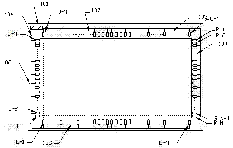
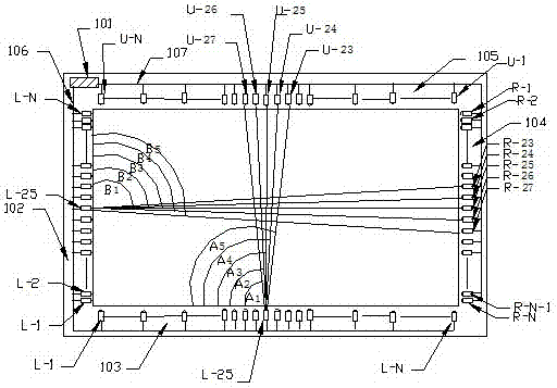
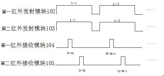
[0033] Such as figure 1 As shown, it is a schematic structural diagram of an infrared touch positioning device in the present invention, the device includes a control module 101 installed on the frame of the touch screen, a first infrared emitting module 102 installed on the four frames of the touch screen, a second infrared emitting The module 103, the first infrared receiving module 104, the second infrared receiving module 105, the first infrared emitting module 102 and the first infrared receiving module 104, the second infrared emitting module 103 and the second infrared receiving module 105 are respectively arranged on the touch screen frame Above, the first infrared transmitting module 102, the second infrared transmitting module 103, the first infrared receiving module 104, and the second infrared receiving module 105 ...


PUM


Abstract

The invention relates to an infrared positioning technology and infrared positioning equipment, in particular to an infrared touch positioning device and an infrared touch positioning method. The infrared touch positioning device comprises at least two groups of infrared transmitter modules and infrared receiver modules which are correspondingly arranged on four frames of a touch screen, and a control module which is used for controlling the infrared transmitter modules and the infrared receiver modules, wherein infrared transmitting tubes and infrared receiving tubes are respectively arranged in the infrared transmitter modules and the infrared receiver modules; a transmitter module bus simultaneously controls the infrared transmitting tube on the infrared transmitter modules; the control module also controls the infrared transmitter modules through a transmitter module bus; a receiver module bus controls the infrared receiving tubes, which are simultaneously controlled by the transmitter module bus, positioned on different infrared transmitter modules and correspond to all the infrared transmitting tubes in a time-shared mode. The invention also provides the infrared touch positioning method which is high in scanning speed, quick in touch response and low in cost.

Description

technical field [0001] The invention relates to an infrared positioning technology and equipment, in particular to an infrared touch positioning device and method. Background technique [0002] The infrared touch screen has a simple structure, is not subject to current, voltage and static interference, and is suitable for working under certain harsh environmental conditions, and has high stability, high resolution, easy installation, and can be used in computers of all grades. A piece of toughened glass can achieve many advantages such as dustproof, anti-riot, waterproof, etc., which makes the infrared touch screen stand out and become the mainstream product in the touch screen market. [0003] However, the existing infrared touch devices usually connect the infrared receiving module and the infrared emitting module to the same control chip, and the infrared emitting elements in the infrared emitting module and the corresponding infrared receiving elements in the infrared re...

Claims


Application Information

Patent Timeline
Patent Type & Authority Patents(China)
IPC IPC(8): G06F3/042
Inventor 徐响林钟杰婷
Owner HUAWEI TEHCHNOLOGIES CO LTD
Learn More