Metal grid touch screen

A metal grid and touch screen technology, which is applied in the direction of instruments, electrical digital data processing, data processing input/output process, etc., can solve the problem that conductive film cannot realize 3D curved surface application, complex manufacturing process of GF2 structure, medium and large size touch screen Panel requirements and other issues, to achieve real-time response, accurate and fast, easy to debug, and good matching effect

Inactive Publication Date: 2021-11-30
烟台正海科技股份有限公司
View PDF6 Cites 0 Cited by
  • Summary
  • Abstract
  • Description
  • Claims
  • Application Information

AI Technical Summary

Problems solved by technology

[0002] ITO (indium tin oxide) conductive film is an important raw material for making capacitive touch screens. The traditional film structure multi-touch touch screen generally has a GFF structure (Glass-Film-Film, the sensing layer and the driving layer of the touch screen are located in two layers respectively. On the conductive film), GF2 (Glass-Film, the driving layer and the sensing layer of the touch screen are located on the upper and lower sides of the single-layer conductive film) structure, but the GF2 structure manufacturing process is relatively complicated, and the technical threshold is high, so most of the touch terminals on the market The film structure touch screen of the product is generally GFF structure
[0003] However, with the rapid development of consumer electronics, entertainment games, wearable and foldable products, smart homes, education and teaching and other fields, the demand for touch panels or flexible panels of various sizes is becoming more and more urgent, and the above-mentioned traditional ITO conductive film cannot be realized. For 3D curved surface applications, the conductivity cannot meet the requirements of medium and large size touch panels, and ITO is a scarce resource and is not renewable

Method used


Image

  • Metal grid touch screen
  • Metal grid touch screen
  • Metal grid touch screen

Examples


Embodiment Construction

[0032] In order to enable those skilled in the art to better understand the present invention, the technical solutions in the embodiments of the present invention will be clearly and completely described below in conjunction with the accompanying drawings in the embodiments of the present invention, and the described embodiments are only the present invention Some examples, but not all examples. Based on the embodiments of the present invention, all other embodiments obtained by persons of ordinary skill in the art without making creative efforts shall fall within the protection scope of the present invention.

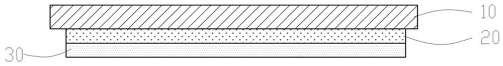
[0033] see figure 1 , the present embodiment provides a metal grid touch screen, and its structure includes a cover plate 10 , an optical adhesive layer 20 , and a metal grid conductive film 30 in sequence from top to bottom.

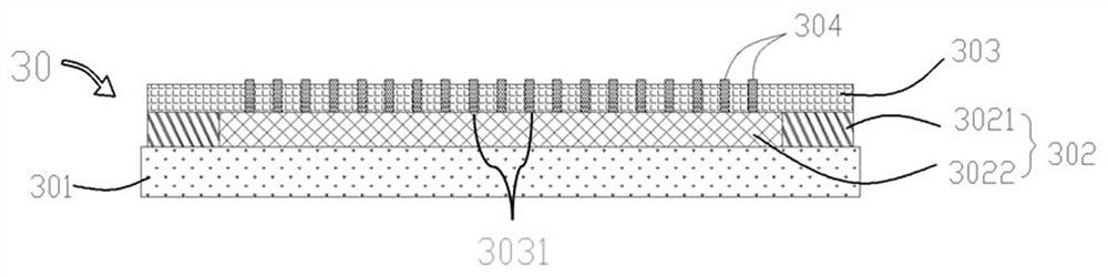
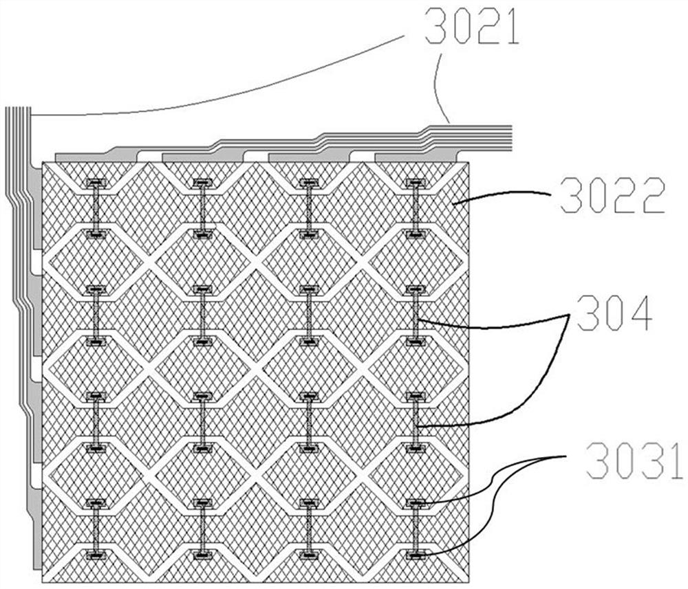
[0034] see figure 2 The metal grid conductive film 30 provided in this embodiment includes a silver paste bonding block 304 , an insulating ...


PUM

PropertyMeasurementUnit
thicknessaaaaaaaaaa
widthaaaaaaaaaa
thicknessaaaaaaaaaa

Abstract

The invention relates to a metal grid touch screen which structurally comprises a cover plate, an optical adhesive layer and a metal conductive film from top to bottom in sequence, the metal conductive film structurally comprises a silver paste lap joint block, an insulating adhesive layer, a conductive pattern and a base material from top to bottom in sequence, and the conductive pattern comprises a metal grid and a frame area wire. The silver paste lap joint blocks are in lap joint with the metal grid through lap joint points, and the lap joint points are not provided with insulating glue layers. The metal grid touch screen provided by the invention is only provided with one layer of metal grid conductive film, realizes multi-point touch control, is simple in manufacturing process, low in cost, capable of realizing mass production, applied to terminal products of various sizes, high in competitiveness and in line with the national sustainable development strategy.

Description

technical field [0001] The present invention relates to the field of touch display, in particular to a touch screen, in particular to a Metal Mesh touch screen. Background technique [0002] ITO (indium tin oxide) conductive film is an important raw material for making capacitive touch screens. The traditional film structure multi-touch touch screen generally has a GFF structure (Glass-Film-Film, the sensing layer and the driving layer of the touch screen are located in two layers respectively. On the conductive film), GF2 (Glass-Film, the driving layer and the sensing layer of the touch screen are located on the upper and lower sides of the single-layer conductive film) structure, but the GF2 structure manufacturing process is relatively complicated, and the technical threshold is high, so most of the touch terminals on the market The film structure touch screen of the product is generally a GFF structure. [0003] However, with the rapid development of consumer electronic...

Claims


Application Information

Patent Timeline
Patent Type & Authority Applications(China)
IPC IPC(8): G06F3/044
CPCG06F3/0446G06F3/0443
Inventor 王焕章刘红艳王文涛董龙龙
Owner 烟台正海科技股份有限公司
Why Eureka
Try Eureka