Chain saw

A chain saw and main body technology, applied in the direction of chain saws, sawing equipment, belts/chains/gears, etc., can solve the problem of small movement and achieve the effect of easy replacement operations

Active Publication Date: 2012-05-16
MAKITA CORP
View PDF10 Cites 9 Cited by
  • Summary
  • Abstract
  • Description
  • Claims
  • Application Information

AI Technical Summary

Problems solved by technology

However, in the linear motion mechanism, the amount of movement of the linear motion element along the rotation axis is relatively small compared to the amount of rotation to rotate the rotation axis.

Method used


Image

  • Chain saw
  • Chain saw
  • Chain saw

Examples


Embodiment 1

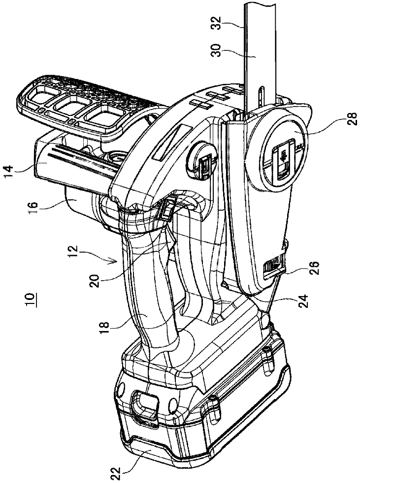
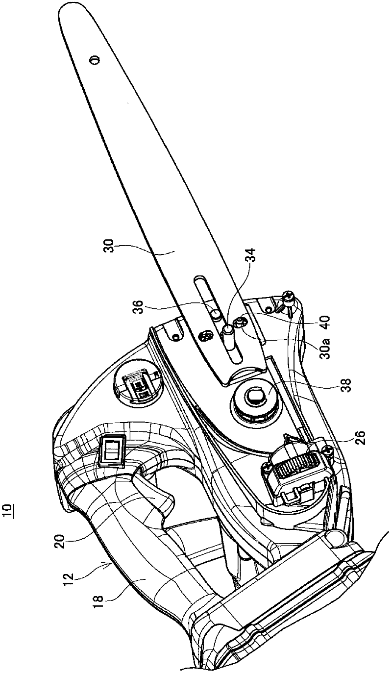
[0025] Hereinafter, embodiments will be described with reference to the drawings. figure 1 The external view of the chain saw 10 is shown. figure 2 The external view of the chain saw 10 in the state which removed the cover 24 and the saw chain 32 from the main body 12 mentioned later is shown. The chain saw 10 includes a main body 12, a saw chain 32 and a guide rod 30 mounted on the main body 12.

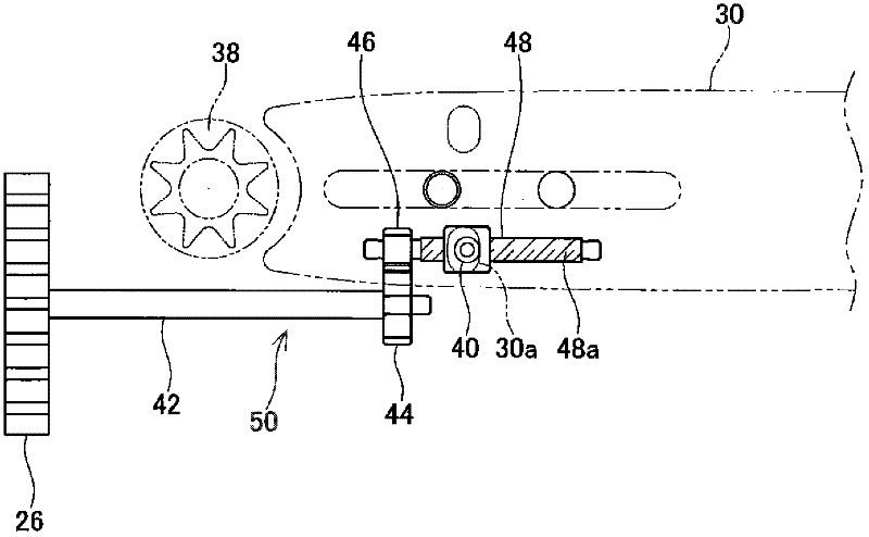
[0026] Such as figure 1 with figure 2 As shown, the main body 12 includes a motor 16, a first handle 14, a second handle 18 and a sprocket 38. A trigger switch 20 for starting the chain saw 10 is provided on the second handle 18. The sprocket 38 is provided on the side surface of the main body 12 and is rotatably supported by the main body 12. The sprocket 38 is connected to the motor 16 and is driven to rotate by the motor 16. The electric motor 16 is supplied with power from the battery 22 in conjunction with the operation of the trigger switch 20. The battery 22 is detachably...


PUM


Abstract

A linear motion mechanism is provided with a second rotating shaft having a male screw thread section (48a) in the area of a part of the second rotating shaft in the longitudinal direction thereof, and an adjustment pin (40) having a through-hole (60) through which the male screw thread section (48a) passes. The through-hole (60) of the adjustment pin (40) has a cross-sectional shape which enables the adjustment pin (40) to move in the radial direction of the second rotating shaft. A female screw thread section (62) which, depending on the position of the adjustment pin (40), engages with and is disengaged from the male screw thread section (48a) of the second rotating shaft is formed on the inner surface of the through-hole (60). A spring (56) capable of holding the engaged state between the male screw thread section (48a) and the female screw thread section (62) is provided to the adjustment pin (40).

Description

Technical field [0001] The invention relates to a chain saw with a linear motion mechanism that moves a linear motion part along a rotating shaft. Background technique [0002] In the specification of German Patent Invention No. 10353737, a chain saw with a linear motion mechanism is disclosed. In this kind of chain saw, the mechanism for adjusting the tension of the saw chain adopts a linear motion mechanism. The linear motion mechanism includes a rotating shaft and a linear moving element engaged with the threaded portion of the rotating shaft. The linear moving part is engaged with the guide rod. The saw chain is tensioned and arranged on the guide rod and the main body across the guide rod and the main body. [0003] When adjusting the tension of the saw chain, the operator operates the hand wheel fixed on the rotating shaft. When the operator operates the handwheel, the rotating shaft rotates and the linear moving part moves along the rotating shaft. As a result, the guid...

Claims


Application Information

Patent Timeline
Patent Type & Authority Applications(China)
IPC IPC(8): B27B17/00B27B17/14F16H25/24
CPCB27B17/14F16H25/2025Y10T83/7239
Inventor 大河内克己
Owner MAKITA CORP
Why Eureka
Try Eureka