Solar cell panel inspecting apparatus, solar cell panel inspecting method, and solar cell panel manufacturing method

A technology for solar panels and inspection devices, which can be used in measuring devices, measuring electricity, photovoltaic power generation, etc., can solve problems such as residues, and achieve the effect of improving productivity and reducing waste.

Inactive Publication Date: 2014-09-10
SHARP KK
View PDF5 Cites 0 Cited by
  • Summary
  • Abstract
  • Description
  • Claims
  • Application Information

AI Technical Summary

Problems solved by technology

But actually, if Figure 24 As shown, the residue 23 of certain materials may remain on the peripheral insulating region 21 during patterning

Method used


Image

  • Solar cell panel inspecting apparatus, solar cell panel inspecting method, and solar cell panel manufacturing method
  • Solar cell panel inspecting apparatus, solar cell panel inspecting method, and solar cell panel manufacturing method
  • Solar cell panel inspecting apparatus, solar cell panel inspecting method, and solar cell panel manufacturing method

Examples


no. 1 approach

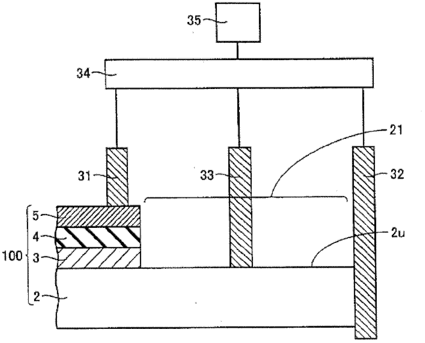
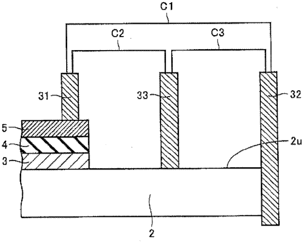
[0038] refer to figure 1 , figure 2 , the solar cell panel inspection device according to the first embodiment of the present invention will be described. The solar cell panel inspection device is used to inspect the insulation performance of the outer peripheral insulating region 21 of the solar cell panel 100. The solar cell panel 100 includes a transparent insulating substrate 2 having a main surface 2u and sequentially laminated on the main surface 2u of the transparent insulating substrate 2. The transparent electrode layer 3, the semiconductor photoelectric conversion layer 4, and the back electrode layer 5 have a peripheral insulating region 21 exposing the main surface 2u of the transparent insulating substrate 2 near the outer periphery of the transparent insulating substrate 2. The solar cell panel inspection device has: a first terminal 31 for abutting against the back electrode layer 5; a second terminal 32 for abutting against the vicinity of the outer peripher...

no. 2 approach

[0051] refer to Figure 14 , Figure 15 , a solar cell panel inspection device according to a second embodiment of the present invention will be described.

[0052] The solar cell panel inspection device of this embodiment is basically the same as the device described in the first embodiment, except that it is further capable of storing reference value data of current. and if Figure 14 Shown is a judging part 36 for comparing the current value detected by the current detecting part with the reference value after a predetermined time has elapsed since the voltage is applied by the voltage applying part, and according to the The comparison result determines whether to continue applying voltage to the two terminals. exist Figure 14 Among them, the reference value data of the voltage is held by the data holding unit 37 , and the judging unit 36 ​​can read appropriate data from the data holding unit 37 .

[0053] Figure 15 A flowchart showing the operation of the solar pan...

no. 3 approach

[0058] refer to Figure 16 , Figure 17 , a solar cell panel inspection device according to a third embodiment of the present invention will be described.

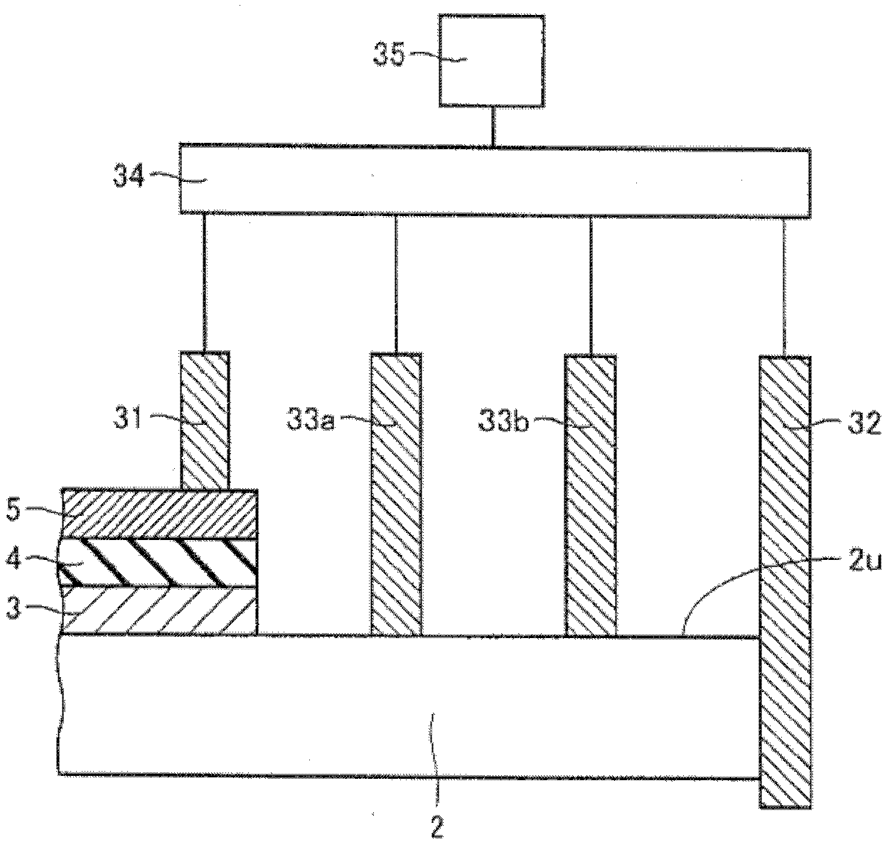
[0059] The solar cell panel inspection device of this embodiment is basically the same as the device described in the first embodiment except that Figure 16 , Figure 17 As shown, there is a third terminal switching mechanism 38, which is used to control the one or more terminals while maintaining the state that the first terminal 31 is in contact with the back electrode layer 5 and the second terminal 32 is in contact with the transparent insulating substrate 2. All or part of the third terminal is switched between a first state in contact with the outer peripheral insulating region 21 and a second state in which it does not contact the outer peripheral insulating region 21 , Figure 16 represents the first state, Figure 17 Indicates the second state. The third terminal switching mechanism 38 can be a one-way switc...


PUM


Abstract

The invention provides a solar panel inspection device, a solar panel inspection method and a solar panel manufacturing method. The solar panel inspection device is a device used to inspect the insulation performance of the outer peripheral insulation area (21) of the solar panel (100). The solar panel includes a transparent insulating substrate (2) with a main surface (2u) and a stacked The transparent electrode layer (3), the semiconductor photoelectric conversion layer (4) and the back electrode layer (5), and has an outer peripheral insulating area (21) exposing the main surface (2u); the solar panel inspection device has a function for communicating with the back surface The first terminal (31) for contacting the electrode layer (5), the second terminal (32) for contacting near the outer peripheral end of the outer peripheral insulating region (21), and the second terminal (32) for connecting the first terminal (31) and the second terminal (31). One or more third terminals (33, 33a, 33b, 33c) between the terminals (32) and in contact with the outer peripheral insulating area (21) are used to apply a voltage between two terminals selected from these terminals. A voltage application unit (34) and a current detection unit (35) that detects a current flowing between the two terminals to which a voltage is applied.

Description

technical field [0001] The invention relates to a solar cell panel inspection device, a solar cell panel inspection method, and a solar cell panel manufacturing method. Background technique [0002] The current solar cell panel has the structure shown in (Japanese) Unexamined Patent Publication No. 2008-109041 (Patent Document 1), and an example of the solar cell panel shown in Patent Document 1 is noted, Figure 23 An enlarged cross-sectional view showing the vicinity of its end. The solar cell panel 100 includes a transparent insulating substrate 2 having a main surface 2u, and a transparent electrode layer 3, a semiconductor photoelectric conversion layer 4, and a back electrode layer 5 sequentially stacked on the main surface 2u of the transparent insulating substrate 2. The solar cell panel 100 is The vicinity of the outer periphery of the transparent insulating substrate 2 has an outer peripheral insulating region 21 exposing the main surface 2 u of the transparent ins...

Claims


Application Information

Patent Timeline
Patent Type & Authority Patents(China)
IPC IPC(8): H02S50/10
CPCG01R31/2605H02S50/10Y02E10/50
Inventor 立花伸介清水彰
Owner SHARP KK
Why Eureka
Try Eureka