
Television camera and television camera control system

A device control and camera technology, applied to TV system components, TVs, color TVs, etc., can solve the complicated operation of TV camera device setting, management, adjustment, reuse, and camera setting. To achieve the effect of shortening the color adjustment time, realizing color signal adjustment at high speed, and reducing the degree of deviation

Active Publication Date: 2012-05-16
ITACHI KOKUSAI ELECTRIC INC
View PDF3 Cites 5 Cited by
  • Summary
  • Abstract
  • Description
  • Claims
  • Application Information

AI Technical Summary

Problems solved by technology

However, in the control device of Patent Document 1, the setting, management, adjustment, reuse, etc. of various setting values ​​(control parameters) of these TV camera devices are not considered at all, and in particular, the number of setting values ​​is not solved. Many times, the problem of complicated settings for each camera

Method used


Image

  • Television camera and television camera control system
  • Television camera and television camera control system
  • Television camera and television camera control system

Examples


Embodiment Construction

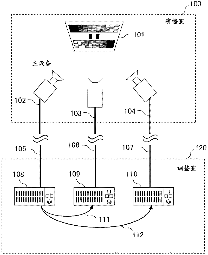
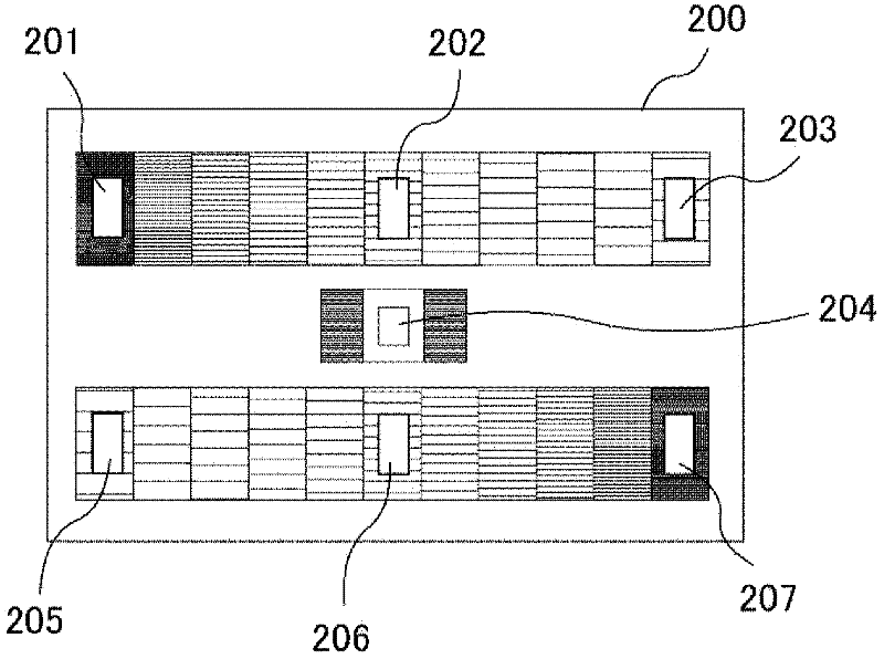
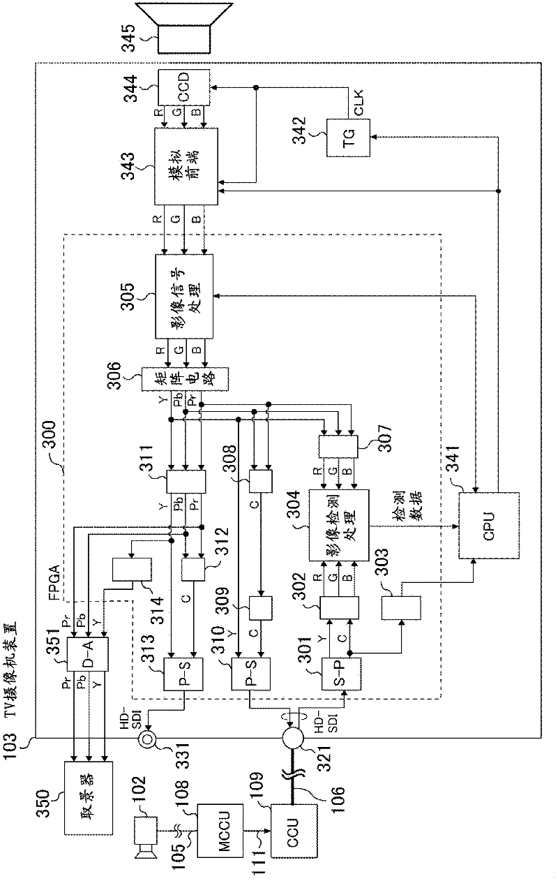
[0046]In the present invention, a serial digital signal (hereinafter, referred to as an SDI (Serial Digital Interface) signal in this specification) of a TV camera device (master) serving as a reference for color signal adjustment is directly input to another computer for color signal adjustment. camera (hereinafter referred to as "slave" in this manual), and automatically adjust the image level of each channel of the slave device, so that the image level of the image signal of each channel of the master device is the same as the image level of each channel of the slave device. The image level of the signal is the same.

[0047] In addition, in the present invention, when a TV camera device and a camera control device (hereinafter referred to as a CCU (Camera Control Unit) in this specification) are used in combination, the video signal of the TV camera device is sent back from the CCU (hereinafter referred to as a CCU in this specification). It is called RET signal in the ins...


PUM


Abstract

Provided is a television camera using a solid-state imaging device, wherein color signal adjustment between TV cameras can be performed easily and quickly without relying on the level of skill of an operator. The serial digital signal of a TV camera (a master) acting as the standard for color signal adjustment is directly input into another TV camera (a slave) that adjusts the color signal, and the image level of each channel of the slave is automatically adjusted in a manner such that the image level of each channel of the master corresponds with that of the slave.

Description

technical field [0001] The invention relates to a method for adjusting color signals between television camera devices. Background technique [0002] In a studio such as a broadcasting station, a plurality of TV camera devices (hereinafter referred to as TV camera devices in this specification) are used simultaneously when producing one broadcast TV program. Here, when a plurality of TV camera devices are used, it is important to mention that there is no color difference among the TV camera devices. [0003] This is because, for example, when there is a color difference between TV camera device A and TV camera device B, when switching from the video captured by TV camera device A to the video captured by TV camera device B, the color tone of the video being broadcast will be different. Changes that make viewers feel uncoordinated. [0004] In order to solve the above-mentioned color deviation among the TV camera devices, when a plurality of TV camera devices are used at th...

Claims


Application Information

Patent Timeline
Patent Type & Authority Applications(China)
IPC IPC(8): H04N9/04H04N5/232H04N17/02
CPCH04N17/002H04N5/232H04N23/60H04N23/662H04N23/634
Inventor 小田原宗明
Owner ITACHI KOKUSAI ELECTRIC INC
Learn More