Vacuum cleaner nozzle with rotatably limited base plate

A vacuum cleaner and rotation angle technology, applied in the direction of the suction nozzle, etc., can solve the problems of inability to distribute the flow, user effort, air leakage, etc., to achieve the best cleaning effect

Active Publication Date: 2012-05-23
SEB SA
View PDF7 Cites 22 Cited by
  • Summary
  • Abstract
  • Description
  • Claims
  • Application Information

AI Technical Summary

Problems solved by technology

On the other hand, this system in particular has the disadvantage of causing air leaks on the side opposite the recess as a function of the pressure-flow moment of the vacuum cleaner, which in many cases impairs the vacuuming efficiency because it cannot Proper distribution of flow along the raised sc

Method used


Image

  • Vacuum cleaner nozzle with rotatably limited base plate
  • Vacuum cleaner nozzle with rotatably limited base plate
  • Vacuum cleaner nozzle with rotatably limited base plate

Examples


Embodiment Construction

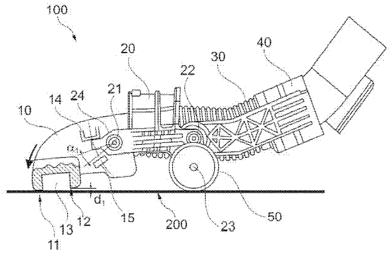
[0018] figure 1 A side view of a suction nozzle 100 of a vacuum cleaner is shown, wherein the suction nozzle 100 is pushed forward over a floor 200 to be cleaned. The suction nozzle 100 of the vacuum cleaner mainly includes a base 10 , the base 10 is connected with a transmission rod 20 , and the transmission rod 20 is connected with the rest of the vacuum cleaner through a connecting piece 40 and a rotating shaft 22 . In addition, the air drawn in flows through the flexible tube 30 which is arranged between the base and the connection piece 40 . The base 10 is rotatable about an axis 21 relative to a transmission rod 20 comprising at least one ground support roller 50 rotatable about an axis 23 to facilitate the use of the suction nozzle 100 . When the suction nozzle 100 moves forward, the user's pushing force is decomposed into a downward vertical component and a forward horizontal component. The roller 50 absorbs the vertical component on the ground, so it is easy for the...


PUM


Abstract

The nozzle (100) has a base plate (10) cleaning a floor with airflow-pressure and connected to a connecting rod (20). A limiting unit i.e. stop (14), limits rotation of the base plate to rotation angle (alpha1) with respect to the connecting rod, where the angle is a function of value of the airflow-pressure and proportional to the airflow-pressure. The stop unit is arranged on the connecting rod and on the base plate. The stop includes a cylindrical part fitted on the connecting rod and on the base plate, where the part possesses length representing a value of the angle.

Description

technical field [0001] The present invention generally relates to vacuum cleaner nozzles with rotatably movable bases. Background technique [0002] It is known in the prior art that the base is rotated for the nozzle of a vacuum cleaner adapted to the direction of the cleaning movement. In particular, document EP1443842 describes a suction nozzle for a vacuum cleaner, the base of which comprises a suction channel delimited by two scraping boundaries and which can be rotated around an axis by a defined angle in order to ensure, depending on the direction of movement, a contact ratio with the ground and One or the other of the two scraping edges makes more contact. Scratching refers to the mechanical action of the base on the fur of the textile floor that is to be cleaned. As a result, the one scraping edge and the lower part of the base that are in contact with the ground act more strongly on the fleece hairs and the other scraping edge is lifted from the ground surface in...

Claims


Application Information

Patent Timeline
IPC IPC(8): A47L9/02
CPCA47L9/02
Inventor 赛里·吉诺弗雷德里克·唐居伊
Owner SEB SA
Why Eureka
Try Eureka