

Rake-type pulling hook for continuous suture
A rake-type and hook-pulling technology, applied in the field of rake-type hooks, can solve the problems of prolonged operation time, prolonged operation time, uneven suture tension, etc. Effect
Inactive Publication Date: 2012-05-23
张石江 +1
View PDF5 Cites 0 Cited by
- Summary
- Abstract
- Description
- Claims
- Application Information
AI Technical Summary
Problems solved by technology
In the first method, the tightening of the needle increases the operation time, and often causes poor exposure in the delicate operation site, making the operation difficult; in the second method, on the one hand, the operation time is prolonged when pulling the hook to find the thread, and On the one hand, due to factors such as thread tension and friction, generally three to four stitches have to be tightened, so that one suture site often needs to be tightened multiple times, which can easily lead to prolonged operation time and even uneven suture tension.
Method used
View moreImage
Smart ImageViewing Examples

Examples
Embodiment Construction
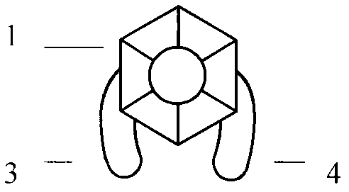
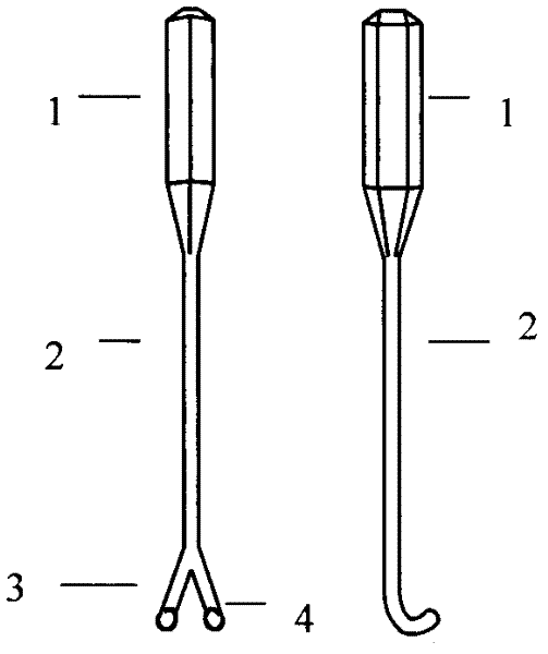
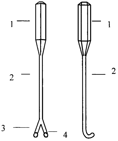
[0010] In the figure, the pull hook is made of metal, the top is prismatic, forming a pull hook handle (1), and the bottom is a thinner cylinder, forming a pull hook rod (2). There is a first pull on the pull hook rod (2). Hook (3) and the second pull hook (4).
[0011] figure 1 It can be seen that there is an angle deviation between the first pull hook (3) and the second pull hook (4).
[0012] figure 2 It can be seen that the first pull hook (3) and the second pull hook (4) are deviated at an angle, and the near end of the pull hook rod is split side by side to form a target pull hook.
Login to View More PUM
 Abstract
The invention discloses a rake-type pulling hook for surgery continuous suture, wherein the pulling hook is made of medical stainless steel or titanium alloy; the upper part of the pulling hook is thicker, prism-shaped and a pulling hook handle; the lower part of the pulling hook is a finer cylindrical rod, which is a pulling hook rod; and two guy hooks arranged in parallel and deflecting a certain angle are arranged at the tail end of the pulling hook rod so as to form the rake-type pulling hook. In the suture time, threads are hung each line hanging hook every 3-4 needles; when the line is tightened, the threads are orderly taken down; the threads and the pulling hook are tightened; and when suturing wound, the wound can be sutured for a plurality of needles, and the rake-type pulling hook helps to ensure uniform thread tension.
Description
Technical field [0001] The invention relates to a rake-type hook used in surgical operations, which can be easily operated during continuous suturing and improves the suturing speed and quality. Background technique [0002] At present, in the known surgical continuous suture operation, two ways are commonly used to tighten the thread: one is to tighten the thread every stitch, and the second is to tighten the thread with a nerve pull hook after sewing several stitches. In the first method, the tightening of the needle increases the operation time, and often causes poor exposure in the delicate operation site, making the operation difficult; in the second method, on the one hand, the operation time is prolonged when pulling the hook to find the thread, and On the one hand, due to factors such as thread tension and friction, generally three to four stitches have to be tightened, so that one suture site often needs to be tightened multiple times, which can easily lead to prolo...
Claims
Login to View More Application Information
Patent Timeline
 IPC IPC(8): A61B17/04
Inventor张石江
Owner张石江