Novel oil press structure
A hydraulic press, a new type of technology, applied to the mechanism field of hydraulic presses, can solve problems such as inconvenience in production and use, and achieve the effects of convenient production and use, and convenient and adjustable space position.
Inactive Publication Date: 2012-05-23
韩士军
View PDF0 Cites 0 Cited by
- Summary
- Abstract
- Description
- Claims
- Application Information
AI Technical Summary
Problems solved by technology
[0002] The hydraulic press is a kind of forging equipment with a large amount of use and a wide range of applications. At present, in the mechanism of the hydraulic press, the fuselage has a fixed structure. Due to this structure, the spatial direction of the workbench of the fuselage It is also fixed. However, in actual work, because the workpiece is often irregular, and for the convenience of feeding the workpiece, it is often necessary to change the orientation or angle of the fuselage workbench in space. Sometimes, in order to install automatic feeding or The convenience and needs of the feeding device also requires changing the orientation and angle of the workbench in the space, which brings a lot of inconvenience to production and use.
Method used
View moreImage
Smart ImageViewing Examples

Examples
Embodiment Construction
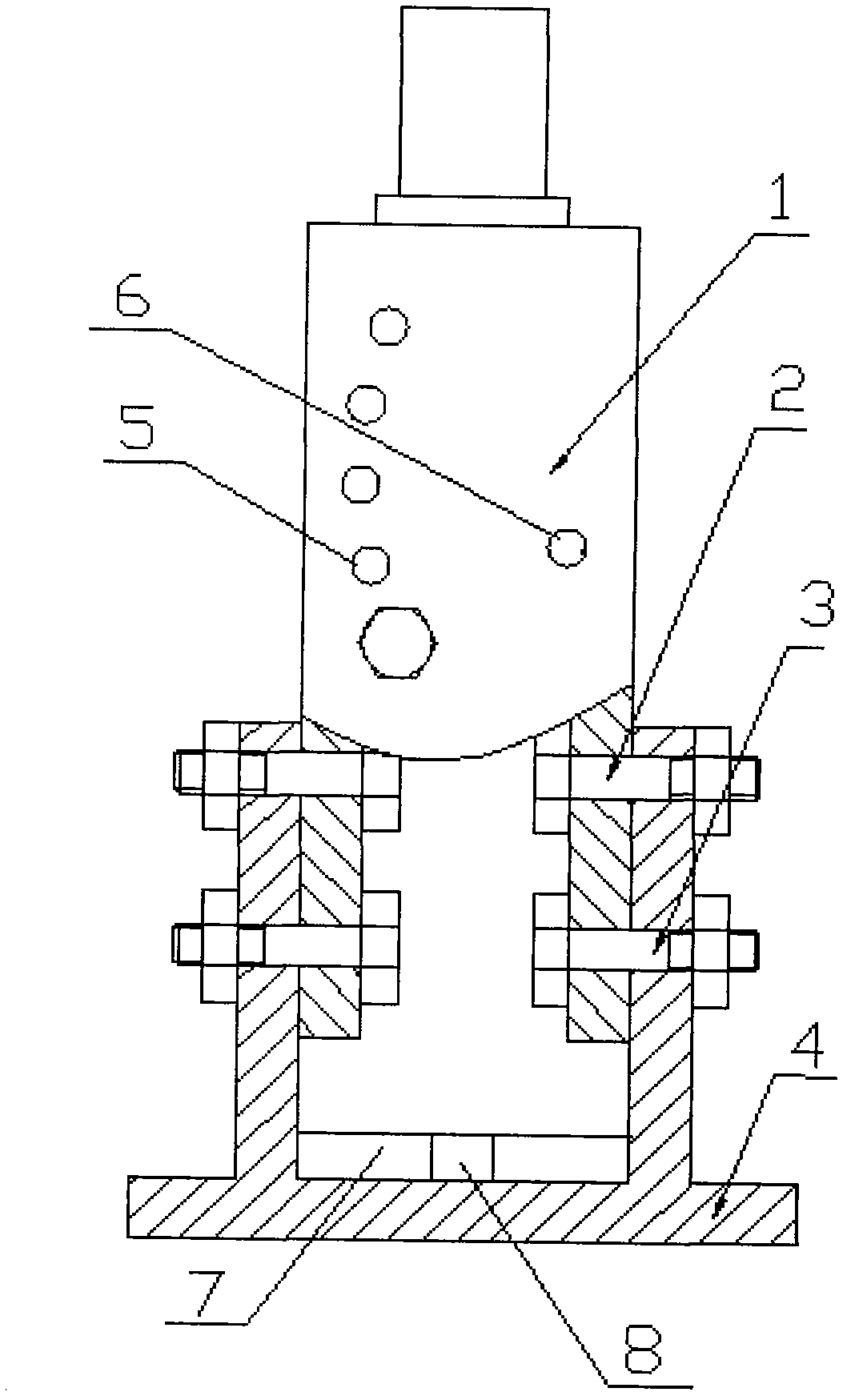
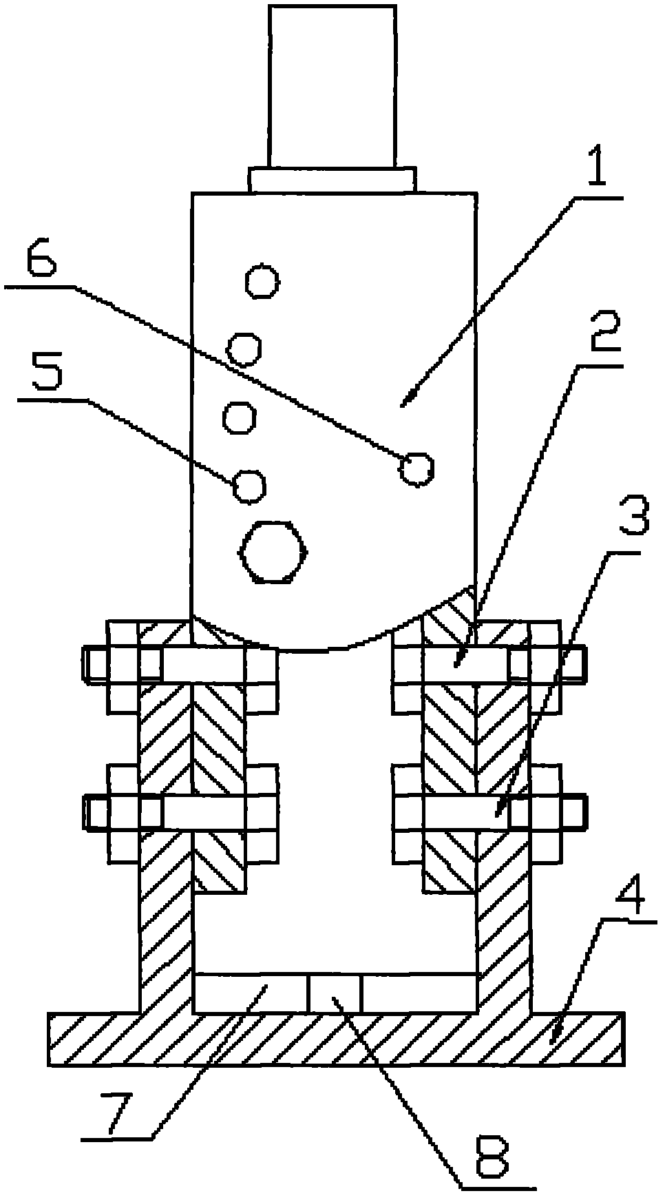
[0008] Install the fuselage (1) on the U-shaped bracket (4) through the corresponding through hole (6) and adjustment hole (5) on the U-shaped bracket (4) with the positioning bolt (3) and the adjusting bolt (2). , the U-shaped bracket (4) is provided with a bracket oil channel (7) and a bracket oil hole (8), and the bracket oil channel (7) and the bracket oil hole (8) are installed with a U-shaped bracket (4) through threaded cooperation. )above.
Login to view more PUM
 Abstract
The invention discloses a novel oil press structure, wherein a machine body of the oil press is arranged on a U-shaped bracket through corresponding through holes and regulating holes on the U-shaped bracket by locating bolts and regulating bolts; a bracket oil duct and a bracket oil hole are arranged on the U-shaped bracket; and the bracket oil duct and the bracket oil hole are arranged on the U-shaped bracket in a threaded fit manner. According to the novel oil press structure, the spatial position of the machine body is convenient and adjustable, so that much convenience is brought to production and use.
Description
technical field [0001] The invention relates to a structure of a hydraulic press, in particular to a structure of a novel hydraulic press, and belongs to the technical field of hydraulic press mechanisms. Background technique [0002] The hydraulic press is a kind of forging equipment with a large amount of use and a wide range of applications. At present, in the mechanism of the hydraulic press, the fuselage has a fixed structure. Due to this structure, the spatial direction of the workbench of the fuselage It is also fixed. However, in actual work, because the workpiece is often irregular, and for the convenience of feeding the workpiece, it is often necessary to change the orientation or angle of the fuselage workbench in space. Sometimes, in order to install automatic feeding or The convenience and needs of the feeding device also require changing the orientation and angle of the fuselage workbench in space, which brings a lot of inconvenience to production and use. Co...
Claims
Login to view more Application Information
Patent Timeline
 IPC IPC(8): B30B15/04
Inventor 韩士军
Owner 韩士军
- R&D Engineer
- R&D Manager
- IP Professional
Why Eureka
- Industry Leading Data Capabilities
- Powerful AI technology
- Patent DNA Extraction
Try Eureka
Browse by: Latest US Patents, China's latest patents, Technical Efficacy Thesaurus, Application Domain, Technology Topic.
© 2024 PatSnap. All rights reserved.Legal|Privacy policy|Modern Slavery Act Transparency Statement|Sitemap