
Slider for slide fastener

A slider and zipper technology, which is applied in the field of sliders for zippers, can solve the problems of falling off of the slider, reduction of the joint strength of the clamping part and the slider, etc., and achieves the effect of improving the operation rate and improving the appearance design.

Active Publication Date: 2012-05-23
YKK CORP
View PDF4 Cites 3 Cited by
  • Summary
  • Abstract
  • Description
  • Claims
  • Application Information

AI Technical Summary

Problems solved by technology

Therefore, if the handle is assembled on the clamping part after painting, there is a possibility that the angular shape of the part changes due to the film laminated on the part where the handle is locked, so that the clamping part and the pull The binding strength of the tab is reduced, and the tab will fall off

Method used


Image

  • Slider for slide fastener
  • Slider for slide fastener
  • Slider for slide fastener

Examples


Embodiment Construction

[0034] Hereinafter, embodiment of the slider for slide fasteners which concerns on this invention is demonstrated in detail based on drawing.

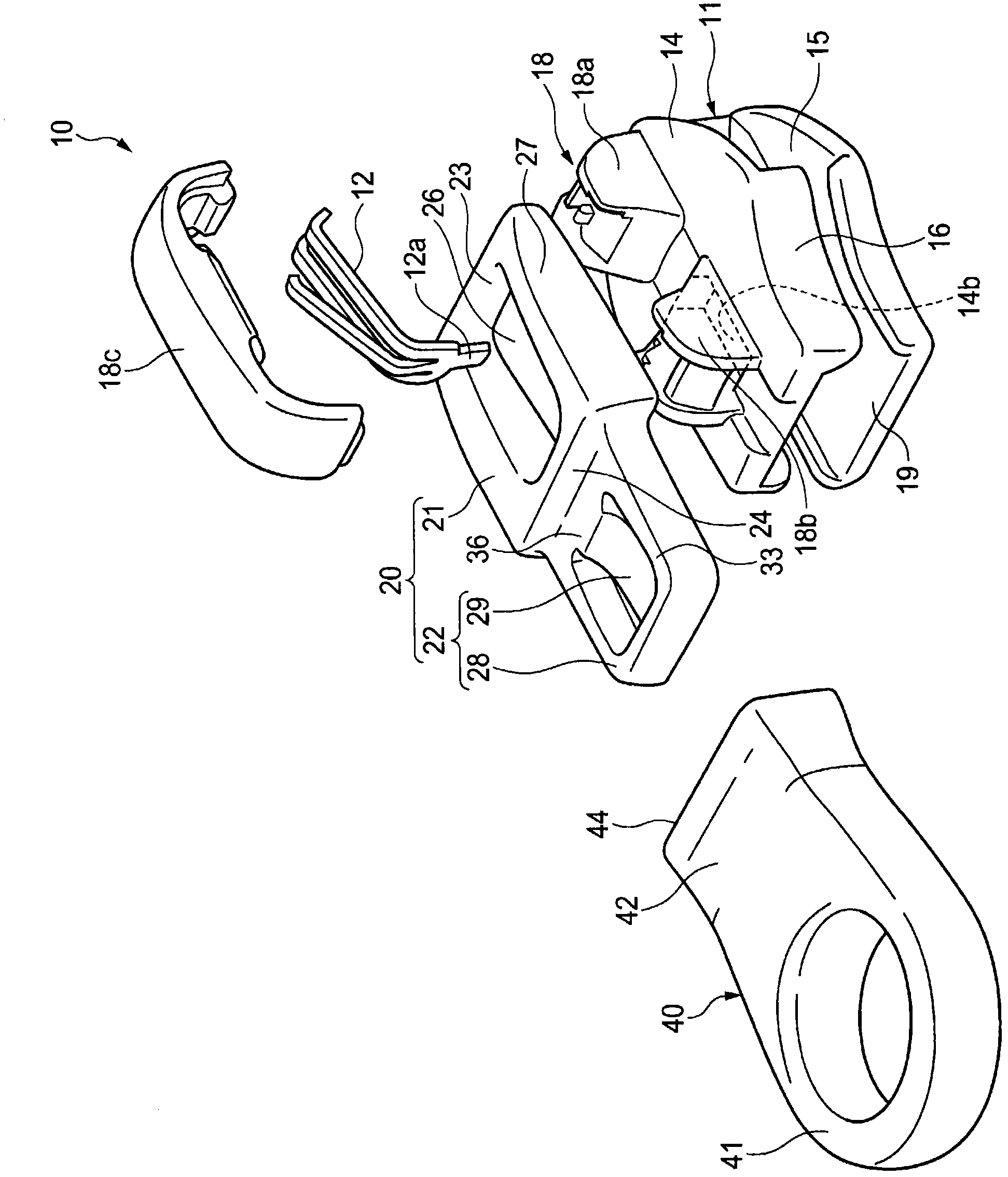
[0035] figure 1 It is an exploded perspective view of the slide fastener slider of the present invention. The slide fastener slider 10 has a slider main body 11 , a lock pin 12 which is an elastic member, a cover 18c constituting a handle mounting post 18 , a clamping portion 20 , and a handle 40 .

[0036] Also refer to Figure 4 (a), (b) and Figure 6 In (a) and (b), the slider main body 11 has: an upper wing plate 14 and a lower wing plate 15 which are arranged side by side separately in the thickness direction and have substantially the same shape as each other; A pair of left and right side wall parts 16 erected on the side edges of the direction; a guide post 17 that is located at the left and right central part of the shoulder side and connects the two wing plates 14, 15; A pair of front and rear mounting post portions 18a, 1...


PUM


Abstract

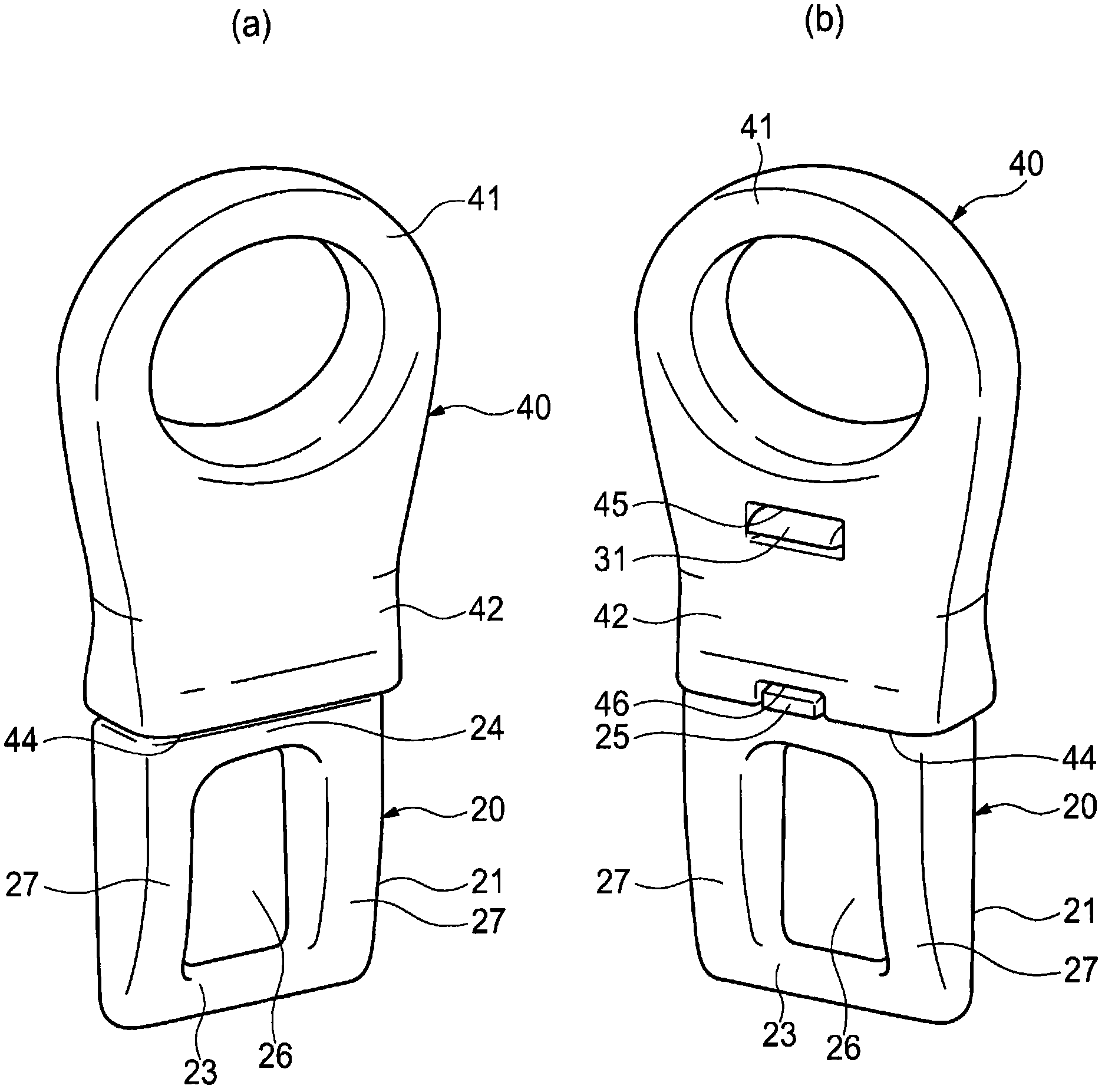
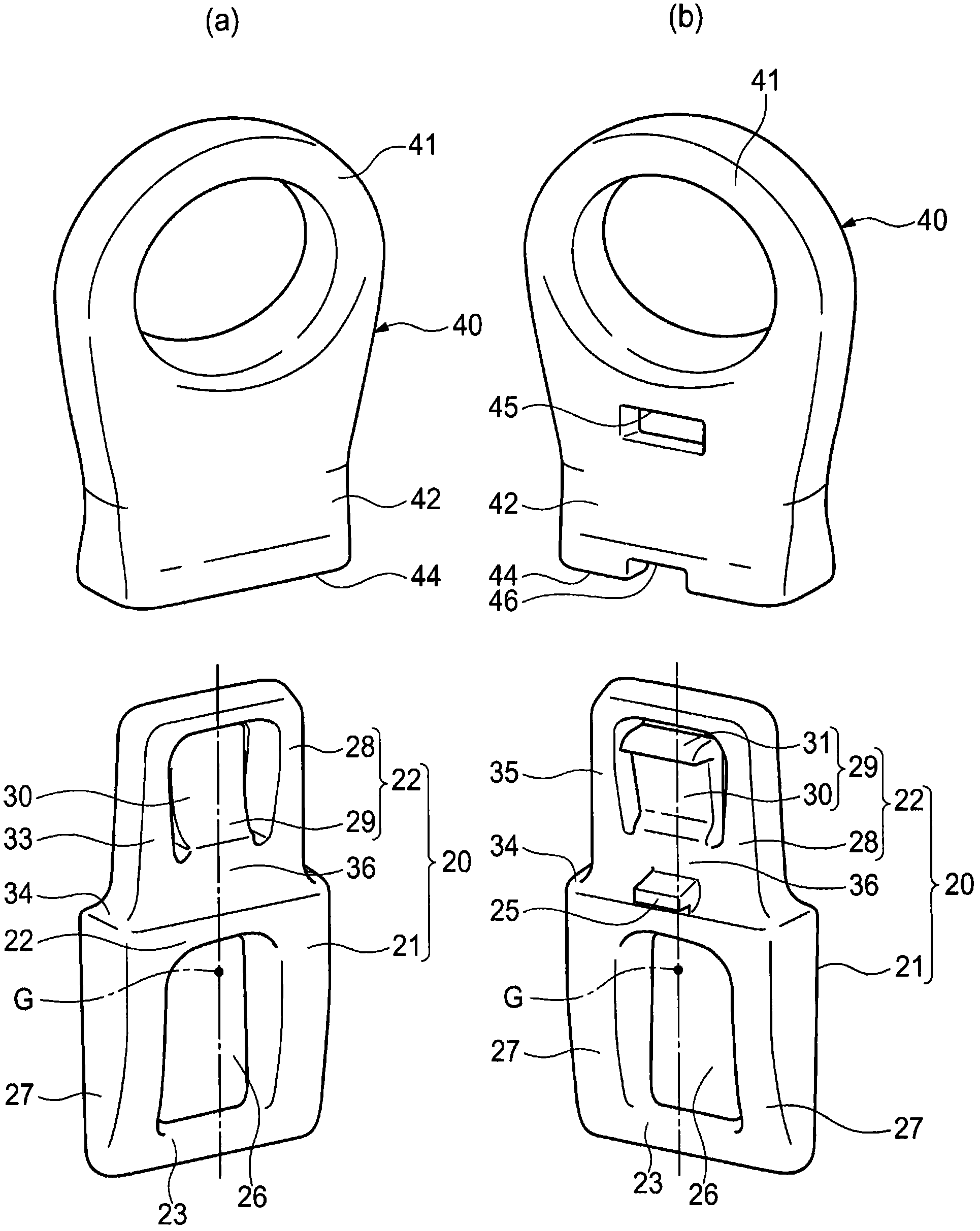
A slider for a slide fastener, provided with a slider body, a clamper, a lock pin, and a cover. The slider is configured so as to be able to be assembled automatically in order that the slider can be mass produced, and the slider is configured in such a manner that a pull tab can be removably mounted to the slider. A slider (10) for a slide fastener is provided mainly with a slider body (11), a clamper (20), and a pull tab (40). A link section (21) of the clamper (20) is mounted to the slider body (11), and the pull tab (40) is mounted to a mounting section (22) of the clamper (20). A projection (25) projecting in the plate thickness direction is formed between the link section (21) and the mounting section (22). When the pull tab (40) is mounted to the clamper (20), the projection (25) is contained in a projection containing section (46) of the pull tab (40).

Description

technical field [0001] The present invention relates to a slider for a slide fastener. More specifically, it relates to a slider for a slide fastener which can attach a slider corresponding to a customer's request to a slider body. Background technique [0002] Conventionally, a slider for a slide fastener is known in which a handle is detachably attached to a slider body, and the handle can be changed according to a customer's request (for example, refer to patent documents 1 and 2.). The slider for a slide fastener described in Patent Document 1 includes a connecting body (clamping portion) attached to the handle attachment portion of the slider main body and a pull tab connected to the connecting body, and the locking tongue of the connecting body is locked to the The locking part of the pull tab is used to connect. In addition, in the slider for a slide fastener described in Patent Document 2, when the locking protrusion provided on the connecting body (clamping part) i...

Claims


Application Information

Patent Timeline
Patent Type & Authority Applications(China)
IPC IPC(8): A44B19/26
CPCA44B19/262
Inventor 槻庆一小泽贵敬熊野隆太
Owner YKK CORP
Learn More