High strength concave type ceiling keel

A high-strength, concave-shaped technology, applied to ceilings, building components, buildings, etc., can solve the problems of poor joint shape and low structural strength, and achieve the effects of small protrusion height, good decorative effect, and improved crack resistance

Inactive Publication Date: 2007-04-18
大连舒心宏业建材有限公司
View PDF0 Cites 2 Cited by
  • Summary
  • Abstract
  • Description
  • Claims
  • Application Information

AI Technical Summary

Problems solved by technology

[0006] The purpose of the present invention is to solve the technical problems of low structural strength and tight combination and poor shape in the prior art, and to provide a strong, durable and tightly combined high-strength concave ceiling keel

Method used


Image

  • High strength concave type ceiling keel
  • High strength concave type ceiling keel
  • High strength concave type ceiling keel

Examples


Embodiment 1

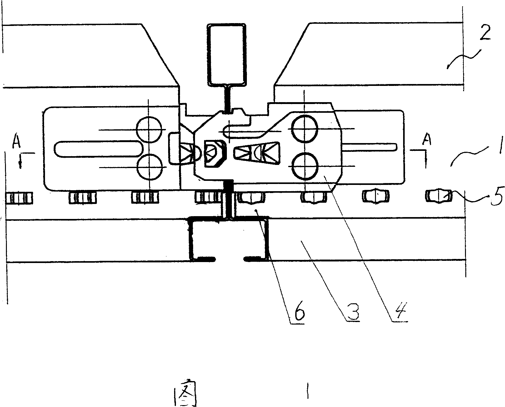
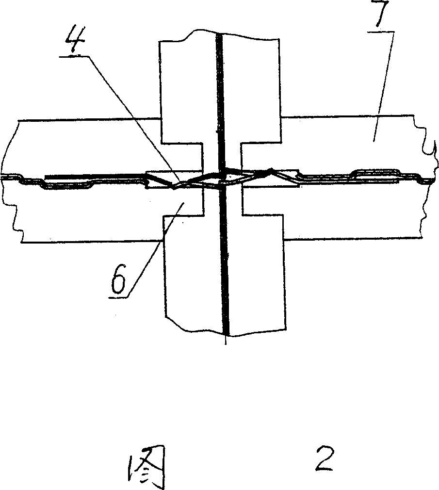
[0021] As shown in Figures 1 and 2: the main keel can be the same as the prior art, and the auxiliary keel is also made of a metal plate folded and pressed together with the prior art. It has a rib plate 1, an upper edge 2 and a lower edge 3, and the rib plate There are ends 4 at both ends of 1, and there are a plurality of occlusal points 5 on the rib plate 1, and at both ends of the rib plate 1 and the lower edge 3, there are lap plates 6 for lapping on the main keel, and the lap plates 6 are in the form of L-shaped, one side is located on the inner top surface 7 of the lower edge 3 , and the other side is located on the rib 1 between the end 4 and the lower edge 3 .

Embodiment 2

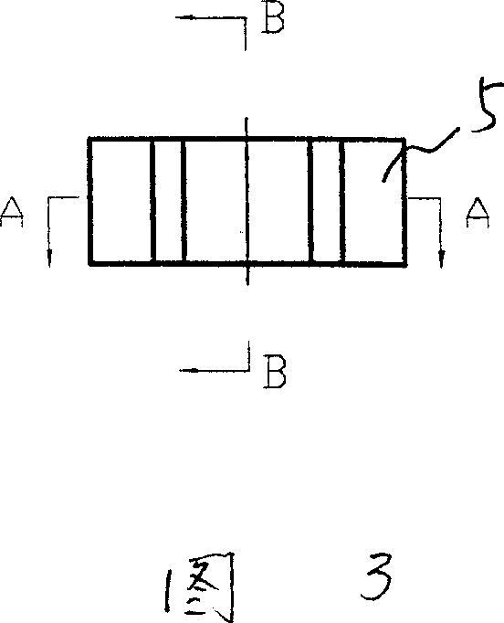
[0023] Others are the same as in Embodiment 1, except that a plurality of occlusal points 5 are in a row. As shown in Figures 3, 4, and 5: the occlusal point 5 is formed by shearing, pressing, stretching, and rolling processes, and its plane protrusion height is 1.57 mm, which is located 10 mm above the bottom edge of the lower edge 3 .

Embodiment 3

[0025] Others are the same as embodiment 1 or embodiment 2, but the end 4 is made of 0Cr18Ni9 / SUS304 stainless alloy steel strip.


PUM


Abstract

This invention discloses a high-intensity concave ceiling keel, comprising a reinforcement plate (1), last edge (2) and under edge (3). There are two ends (4) at the end of the reinforcement plate (1), and multiple points occlusion (5)on the reinforcement plate (1) , lap board (6) at the ends of the reinforcement plate (1) and under edge (3) used for joint with the keel, lap board (6) was L-shaped with one side located in the top surface (7) within lower side of edge (3), another side on the reinforcement plate (1) between end (4) and under edge(3). When the main keel and furring connects, the L-shaped plate set up on furring connected to the main keel, enhance their connectivity, so that enhance the strength of whole skeleton keel; the lap plate makes the main keel and furring bonding tightly, without light on the connect place, with good decorative effect of the ceiling.

Description

Technical field: [0001] The invention relates to a concave ceiling keel used for indoor ceiling decoration, in particular to a durable, tightly combined high-strength concave ceiling keel. Background technique: [0002] At present, most of the indoor ceiling decoration is to insert the main keel and the auxiliary keel to form a skeleton, and then place the ceiling made of fireproof material on the skeleton. The existing main keel and auxiliary keel are all made of a metal plate folded and pressed together, with an upper edge, a rib plate, and a lower edge. There are two rows of pressing points on the rib plate, so that the folded rib plates are combined and pressed The joining point is formed by shearing and pressing a pair of pressing rollers. The plane protrusion height is 1.95mm, and the distance from the lower edge to the bottom edge of the lower row of pressing points is 14mm. There is a long hole in the middle of the main keel, and the reinforcement plate of the auxil...

Claims


Application Information

Patent Timeline
Patent Type & Authority Applications(China)
IPC IPC(8): E04B9/06
Inventor 丛文滨
Owner 大连舒心宏业建材有限公司
Why Eureka
Try Eureka