Striking device

A technology of impact tools and impact hammers, applied in the direction of motor tools, manufacturing tools, etc., can solve the problems of damaged workpieces and low workability, and achieve the effects of suppressing torque loss, convenient operation, and convenient use

Inactive Publication Date: 2012-05-23
MAKITA CORP
View PDF8 Cites 2 Cited by
  • Summary
  • Abstract
  • Description
  • Claims
  • Application Information

AI Technical Summary

Problems solved by technology

[0003] Using such an impact tool, for example, when tightening a screw on the bottom hole, at first, process the bottom hole with an electric drill, and then perform the screw tightening operation with an impact tool such as an impact driver, that is, to complete such an operation, different tools are required. tools, which require preparation and exchange of tools, resulting in poor workability
If you attach a drill to the impact driver, you can perforate. However, if you are processing fragile workpieces such as tiles, the impact force may cause damage to the workpiece.

Method used


Image

  • Striking device
  • Striking device
  • Striking device

Examples


Embodiment approach 1

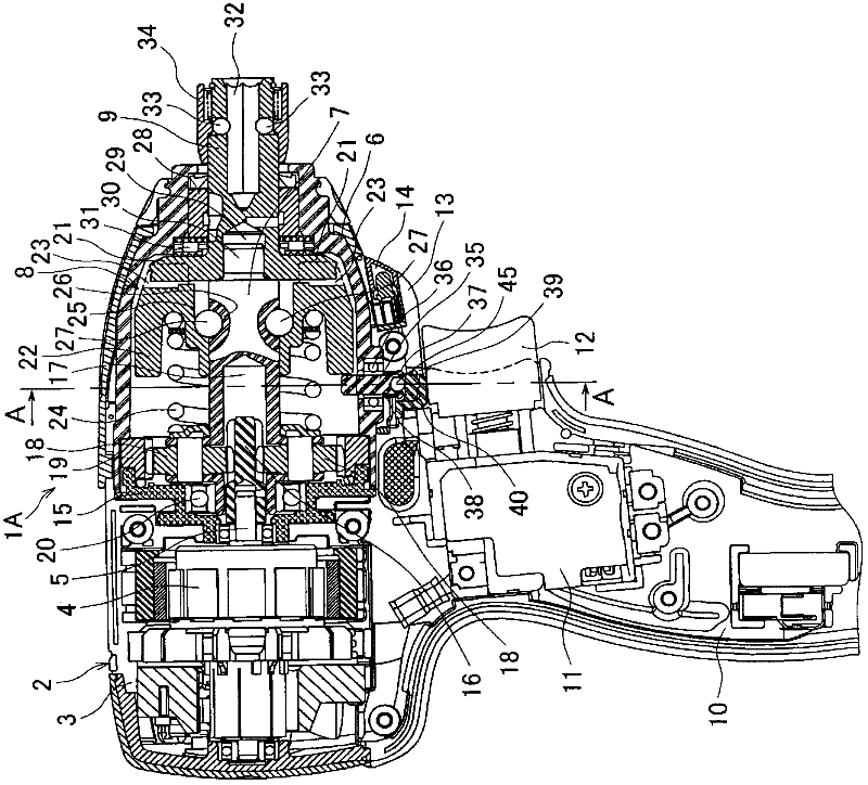
[0031] Such as figure 1 As shown, an impact driver 1A as an example of an impact tool has a main body shell 2 and an impact hammer cover 6, wherein the main body shell 2 is assembled from a pair of half shells 3 with left and right halves, and accommodates a motor 4; Impact hammer cover 6 is the shell that is used to receive main shaft 7, impact mechanism 8, anvil 9, and its section is bell-shaped, is installed in the place ahead of above-mentioned main body shell 2 ( figure 1 center right). Below the main body shell 2 is provided with a handle 10, the handle 10 is extended downwards, a battery pack (not shown) as a power supply is installed at its lower end, and a switch 11 with a trigger 12 is housed in the upper part of the handle 10. An extension part 13 is provided on the main body case 2 . The extension part 13 is located below the hammer cover 6 and between the hammer cover 6 and the trigger 12 , and covers the lower part of the hammer cover 6 . Inside the front side ...

Embodiment approach 2

[0054] exist Figure 4 The illustrated impact driver 1B is different from Embodiment 1 in that the operating member does not slide in the left-right direction but rotates. In front of the stopper pin 35, the pivot pin 50 facing downward is fixed on the lower part of the impact hammer cover 6, and the middle part of the switching handle 51 is pivotally supported on the pivot pin 50. The outside of the extension part 13 is exposed. In addition, an arc-shaped mode switching block 52 is connected to the rear end of the switching handle 51. A recess 41 is formed on the upper surface of the mode switching block 52. The recess 41 includes a first contact surface 42. , the second contact surface 43 and the inclined surface 44 . Make the head end of the switch operation handle 51 rotate in the left and right directions, so as to Figure 5 As shown, the mode switching block 52 is moved in the left-right direction along an arc trajectory around the pivot pin 50 , and the first abutting...

Embodiment approach 3

[0060] exist Figure 8 The illustrated impact driver 1C is different from Embodiment 2 in that two stopper pins 35 that are expandable and contractible in the radial direction of the hammer cover 6 are provided. Specifically, as Figure 10 As shown, a pair of stop pins 35 are respectively pivoted by ball bearings 36, and the pair of stop pins 35 pass through the axis of the main shaft 7 and are left-right symmetrical with respect to a straight line in the up-down direction, and are inclined at a predetermined angle relative to the straight line. , the stopper pin 35 is biased toward the retracted position downward by the coil spring 38 . In addition, the extension part 13 is formed in an arc shape (viewed from the front), and is located on the lower side of the impact hammer cover 6 including the pair of stopper pins 35, and the mode switching dial 53 is provided in the extension part 13. Recesses 41 are respectively formed at both ends of the mode switching disc 53 , and th...


PUM


Abstract

Disclosed is an impact driver such that it is possible to make a changeover to a drill mode without impairing workability. The impact driver (1A) is provided with a stop pin (35) which, forward of a handle (10), protrudes into a hammer case (6) in the lower part of the hammer case (6), and is slidable between a protrusion position and a retreat position, the aforementioned protrusion position being a location where the stop pin (35) engages a hammer (22) in an advanced position to restrict the retreat of the hammer (22), and the aforementioned retreat position being a location where the stop pin (35) disengages the hammer (22) to allow the same to retreat; a coil spring (38) which applies force to press the stop pin (35) to the retreat position; and a mode changeover button (40) which, by being operated from the outside, resists the force applied by the coil spring (38) and causes the stop pin (35) to slide from the retreat position to the protrusion position. When the stop pin (35) is moved to the protrusion position by means of the mode changeover button (40), then the retreat of the hammer (22) is restricted and thereby the hammer (22) is prevented from engaging or disengaging arms (21, 21), with the result that an anvil (9) is made to rotate integrally with a spindle (7).

Description

technical field [0001] The present invention relates to an impact tool such as an impact driver, which has an anvil protruding forward from a casing, and the driver can generate a rotational impact force on the anvil. Background technique [0002] An impact tool such as an impact driver has a main shaft, an impact hammer, an anvil, and a coil spring. The main shaft is located in the housing and can be driven to rotate by a motor; A ball is embedded, and the two are connected by the ball. In addition, a pair of claws are protrudingly provided on the front surface of the impact hammer; the anvil is pivoted on the housing and coaxial with the impact hammer, which is used to install the front end of the working head Extending to the front of the housing, a pair of arms are formed at the rear end in the radial direction; the coil spring is used to load the impact hammer to the forward position where the above claw and the arm are engaged in the rotation direction. That is, when ...

Claims


Application Information

Patent Timeline
Patent Type & Authority Applications(China)
IPC IPC(8): B25B21/02
CPCB25B21/00B25B21/026
Inventor 平林德夫杉本学江口健太
Owner MAKITA CORP
Why Eureka
Try Eureka