Striking device
A technology of impact tools and impact hammers, applied in the direction of motor tools, manufacturing tools, etc., can solve the problems of damaged workpieces and low workability, and achieve the effects of suppressing torque loss, convenient operation, and simple switching operations
- Summary
- Abstract
- Description
- Claims
- Application Information
AI Technical Summary
Problems solved by technology
Method used
Image
Examples
Embodiment approach 1
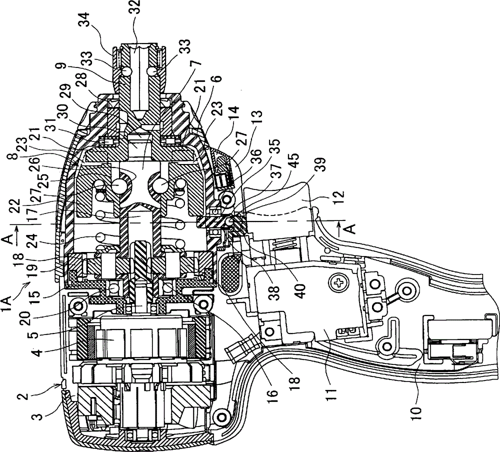
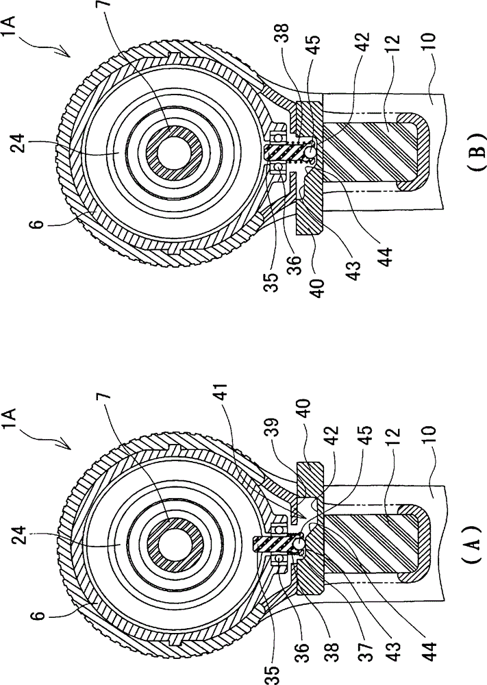
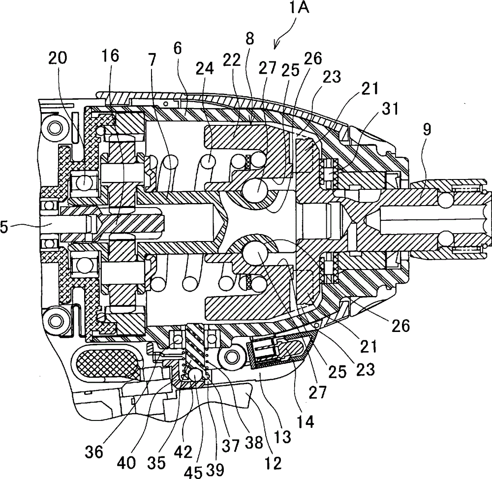
[0031] Such as figure 1 As shown, an impact driver 1A as an example of an impact tool has a main body shell 2 and an impact hammer cover 6, wherein the main body shell 2 is assembled by a pair of left and right half shells 3, and houses a motor 4; The impact hammer cover 6 is a shell used to house the main shaft 7, the impact mechanism 8, and the anvil 9. Its cross-section is in the shape of a bell and is installed in front of the main body shell 2 ( figure 1 Middle right). A handle 10 is provided below the main body shell 2. The handle 10 extends downwards. A battery pack (not shown) as a power source is installed at its lower end. A switch 11 with a trigger 12 is housed in the upper part of the handle 10. An extension 13 is provided on the main body shell 2. The extension 13 is located below the impact hammer cover 6 and between the impact hammer cover 6 and the trigger 12 and covers the lower part of the impact hammer cover 6. A lighting unit 14 is installed inside the front...
Embodiment approach 2
[0054] in Figure 4 In the illustrated impact driver 1B, the operating member does not slide in the left-right direction, but is of a rotary type, which is different from the first embodiment in this point. In front of the stopper pin 35, a pivot pin 50 facing downward is fixed to the lower part of the impact hammer cover 6, the middle part of the switching handle 51 is pivotally supported on the pivot pin 50, and the front part of the switching handle 50 faces The outside of the extension 13 is exposed. In addition, an arc-shaped mode switching block 52 is connected to the rear end of the switching handle 51. A concave portion 41 is formed on the upper surface of the mode switching block 52. The concave portion 41 includes a first contact surface 42 , The second contact surface 43 and the inclined surface 44. Rotate the head end of the switching handle 51 in the left and right directions, so as Figure 5 As shown, the mode switching block 52 is moved along a circular arc traje...
Embodiment approach 3
[0060] in Figure 8 The illustrated impact driver 1C is provided with two stop pins 35 that can expand and contract in the radial direction of the impact hammer cover 6, which is different from the second embodiment in this point. Specifically, such as Picture 10 As shown, a pair of stop pins 35 are pivotally supported by ball bearings 36, and the pair of stop pins 35 pass through the axis of the main shaft 7 and are symmetrical with respect to a straight line in the vertical direction, and are inclined at a predetermined angle with respect to the straight line. , The stopper pin 35 is energized by the coil spring 38 to the lower retracted position. In addition, the extension portion 13 is formed in a circular arc shape (viewed from the front) and is located on the lower side of the impact hammer cover 6 including a pair of stop pins 35. The extension portion 13 is provided with a mode switching disk 53. Both ends of the mode switching disk 53 are respectively formed with rec...
PUM
 Abstract
Description
Claims
Application Information
 - R&D
- Intellectual Property
- Life Sciences
- Materials
- Tech Scout
- Unparalleled Data Quality
- Higher Quality Content
- 60% Fewer Hallucinations
Browse by: Latest US Patents, China's latest patents, Technical Efficacy Thesaurus, Application Domain, Technology Topic, Popular Technical Reports.
© 2025 PatSnap. All rights reserved.Legal|Privacy policy|Modern Slavery Act Transparency Statement|Sitemap|About US| Contact US: help@patsnap.com


