
Assembly made of a compensating tank and a master cylinder for a hydraulic motor vehicle brake system

A technology for hydraulic braking and motor vehicles, which can be applied to hydraulic braking transmissions, connecting components, mechanical equipment, etc., and can solve the problem of high cost

Active Publication Date: 2012-05-23
CONTINENTAL AUTOMOTIVE TECH GMBH
View PDF6 Cites 10 Cited by
  • Summary
  • Abstract
  • Description
  • Claims
  • Application Information

AI Technical Summary

Problems solved by technology

For this, it is necessary to manufacture the threads in the master cylinder cost-intensively

Method used


Image

  • Assembly made of a compensating tank and a master cylinder for a hydraulic motor vehicle brake system
  • Assembly made of a compensating tank and a master cylinder for a hydraulic motor vehicle brake system
  • Assembly made of a compensating tank and a master cylinder for a hydraulic motor vehicle brake system

Examples


Embodiment Construction

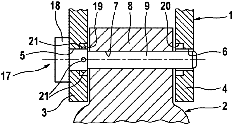
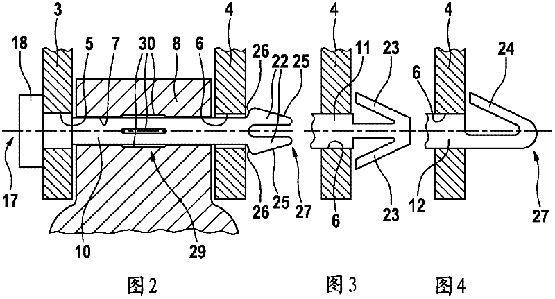
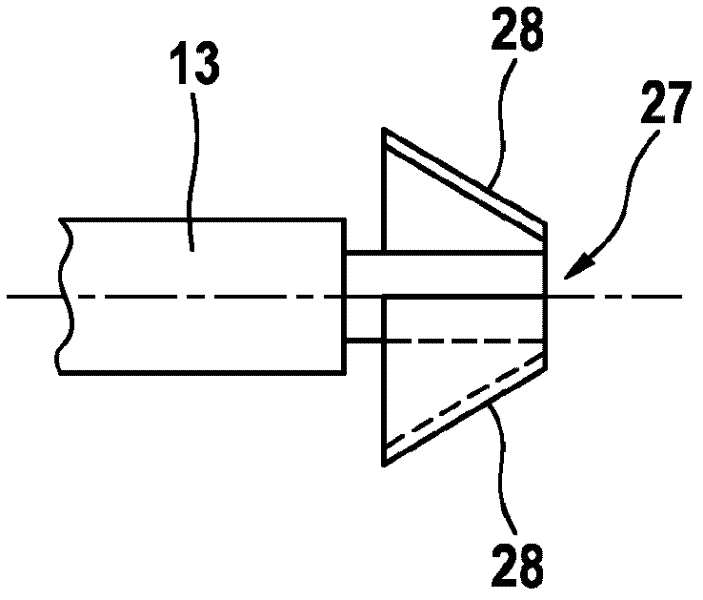
[0030] Figure 1 to Figure 10 An embodiment of an assembly comprising a compensating container 1 and a master cylinder 2 according to the invention is shown schematically for a hydraulic brake system of a motor vehicle, the structure and function of which are basically known. After the compensation container 1 has been mounted on the master cylinder 2, its non-illustrated connection piece is accommodated in a corresponding port of the master cylinder 2, and the pressure medium chamber of the compensation container 1 is connected to the main cylinder in a known manner. The pressure spaces (pressure zones) of cylinders 2 are connected.

[0031] For a releasable connection to the master cylinder 2 , the compensation container 1 has two fastening fittings 3 , 4 which each have an opening 5 , 6 . These openings 5 ​​, 6 are aligned with the opening 7 of the master cylinder 2 after the compensation container 1 has been mounted on the master cylinder 2 . For fastening, fastening pin...


PUM


Abstract

The invention relates to an assembly made of a compensating tank 1 and a master cylinder 2 for a hydraulic motor vehicle brake system, wherein the compensating tank 1 has two fastening attachments 3, 4, each with an opening 5, 6, wherein openings 5, 6 align with an opening 7 in master cylinder 2, and compensating tank 1 is fastened by a detachable connection by means of a fastening pin 9; 10; 11; 12; 13; 14; 15; 16 that extends through the aligned openings 5, 6, 7. In order to improve the installation and possible dismantling of the fastening pin, and at the same time to maintain an optimized assembly weight, the invention proposes that fastening pin 9; 10; 11; 12; 13; 14; 15; 16 be made of plastic and interact in a positive- or force-locking manner with at least one of the openings 5, 6 of fastening attachments 3, 4.

Description

technical field [0001] The invention relates to an assembly for a hydraulic brake system of a motor vehicle comprising a compensating container and a master cylinder, wherein the compensating container has two fastening attachments each having an opening, wherein the openings are connected to the master cylinder The compensating container is fixed in a releasable (releasable) connection by means of a fastening pin which extends through said aligned opening. Background technique [0002] Such an assembly is known, for example, from DE 100 47 325 A1. The fastening pin known therefrom is designed as an angled pin and has a projection which can be locked in a spring receptacle connected to the fastening accessory. The angled pin is usually made of stainless steel. The removal from said fastening accessories is carried out by means of tools, which is considered a disadvantage, especially from the point of view of reducing the space in the engine compartment for mounting this as...

Claims


Application Information

Patent Timeline
Patent Type & Authority Applications(China)
IPC IPC(8): B60T17/06B60T11/22B60T11/26F16B5/00F16B15/00F16B21/00
CPCB60T17/06B60T11/22F16B21/086B60T11/26F16B5/0642F16B13/0816F16B5/00
Inventor S·施利希特P·坦德勒H-J·诺伊曼
Owner CONTINENTAL AUTOMOTIVE TECH GMBH
Learn More