Supercharge Your Innovation With Domain-Expert AI Agents!

Planetary gear mechanism

A technology of planetary gears and gears, which is applied to gear transmissions, belts/chains/gears, mechanical equipment, etc., can solve problems such as the inability to achieve large reduction ratios, increase pins, and thinner diameters, and achieve smaller volumes and reductions cost effect

Inactive Publication Date: 2012-05-23
JTEKT CORP
View PDF12 Cites 12 Cited by
  • Summary
  • Abstract
  • Description
  • Claims
  • Application Information

AI Technical Summary

Problems solved by technology

However, in order to increase the number of pins, it is necessary to reduce the diameter of the pins
Such a choice is difficult to achieve in reality, and the result is that a structure with a large reduction ratio cannot be realized

Method used


Image

  • Planetary gear mechanism
  • Planetary gear mechanism
  • Planetary gear mechanism

Examples


Embodiment 1

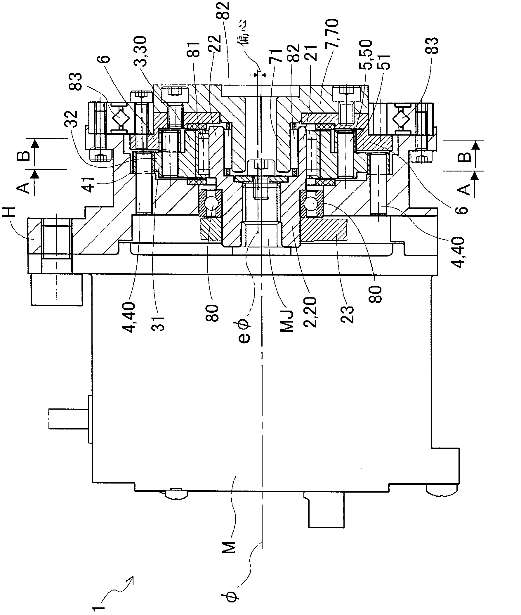
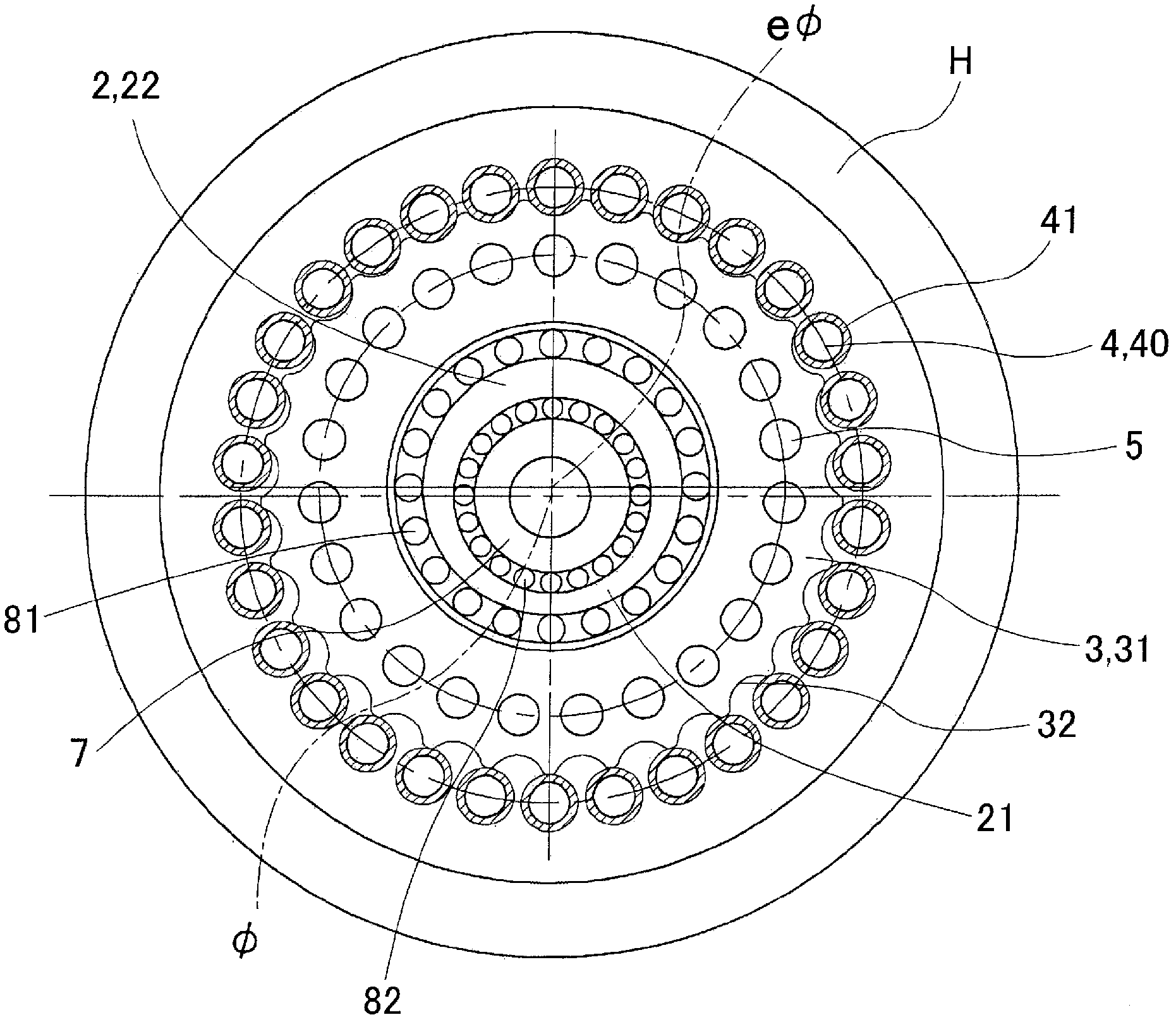
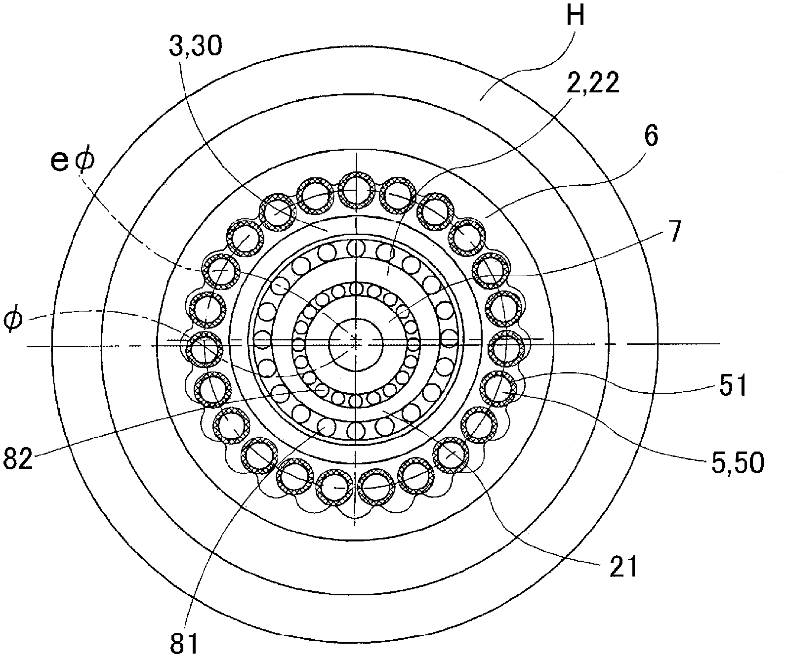
[0072] Below, based on Figure 1 to Figure 5 , Embodiment 1 will be described. figure 1 A speed reduction device using the planetary gear mechanism of this embodiment is shown. In this embodiment, the reduction gear transmission 1 in which the driving force of the motor M input to the input shaft 2 is decelerated and output to the output shaft 7 is shown. Also, to represent the rotation of the input shaft and the phase of the gear, the figure 1 The A-A profile in figure 2 shown in , and will figure 1 The B-B profile in image 3 shown in .

[0073] The reduction gear transmission 1 of this embodiment has a motor M, a housing H, an input shaft 2 , a swing panel 3 , a first pin 4 , a second pin 5 , an internal gear 6 , and an output shaft 7 .

[0074] The motor M (corresponding to the electric motor of the present invention) is a member that outputs rotation. In this embodiment, the motor M is not particularly limited.

[0075] The housing H (corresponding to the first m...

Embodiment 2

[0123] Next, based on Figure 6 ~ Figure 9 , only the differences between the reduction gear transmission 1K according to the second embodiment and the above-mentioned reduction gear transmission 1 will be described. Such as Image 6 As shown, the casing C1 (corresponding to the first component of the present invention) of the motor M1 (corresponding to the electric motor of the present invention) is integrally formed with the casing of the reduction gear 1K. The case C1 also serves as a housing of the reduction gear 1K, and supports the output shaft 700 so that the output shaft 700 (relative to the second member of the present invention) can rotate through the output shaft support bearing 803 (corresponding to the third support bearing of the present invention). . The inner ring of the output shaft support bearing 803 is integrally formed with the output shaft 700 .

[0124] In addition, an output shaft 200 (corresponding to the third member of the present invention and the ...


PUM


Abstract

A planetary gear mechanism (1) of the invention includes a housing H, an input shaft (2) that has an eccentric portion (22) whose center lies on an eccentric axis, and is rotatable about the axis of input and output shafts relative to the housing (H), an oscillating face plate (3) that eccentrically oscillates relative to the input shaft (2) via the eccentric portion (22), and rotates about the eccentric axis, and an output shaft (7) that is provided with a second internally toothed gear that internally contacts and meshes with a second externally toothed gear formed on the oscillating face plate (3), and is rotatable about the axis of the input and output shafts relative to the housing (H). The housing (H) is formed with a first internally toothed gear that internally contacts and meshes with a first externally toothed, gear formed on the oscillating face plate (3). As the input shaft (2) rotates, a circumferential position at which each externally toothed gear meshes with the corresponding internally toothed gear changes, and rotation of the input shaft (2) is transmitted at a reduced speed to the oscillating face plate (3), of which rotation is delivered at a further reduced speed to the output shaft (7).

Description

technical field [0001] The present invention relates to planetary gear mechanisms. Background technique [0002] In order to decelerate the rotation of the motor, etc., a speed reducer having a planetary gear mechanism is used. As this planetary gear mechanism, there is known a planetary gear mechanism having the following configuration: a first shaft; a first shaft; an internal gear for internal meshing with the external gear; and a second shaft connected to the external gear via a unit that transmits only the rotation component of the external gear. In addition, a cycloidal differential planetary gear mechanism is known as a specific example of the planetary gear mechanism. [0003] The reducer using the cycloidal differential planetary gear mechanism, compared with the planetary reducer mechanism with the involute tooth shape of the general gear, has a higher meshing rate and a higher reduction ratio on the basis of obtaining a larger reduction ratio. The advantage of ...

Claims


Application Information

Patent Timeline
Patent Type & Authority Applications(China)
IPC IPC(8): F16H1/32
CPCF16H1/32
Inventor 南云考司太田浩充本田朋宽铃木善晴加藤喜绅
Owner JTEKT CORP
Features
  • R&D
  • Intellectual Property
  • Life Sciences
  • Materials
  • Tech Scout
  • Unparalleled Data Quality
  • Higher Quality Content
  • 60% Fewer Hallucinations
Learn More