
Arrangement of a stepping switch on a control transformer

An adjustable transformer and adjustable technology, applied in the direction of variable transformers, transformers, variable inductors, etc., can solve the problem of more expensive, and achieve the effect of small installation space

Inactive Publication Date: 2012-05-23
MASCHFAB REINHAUSEN GEBR SCHEUBECK GMBH & CO KG
View PDF6 Cites 0 Cited by
  • Summary
  • Abstract
  • Description
  • Claims
  • Application Information

AI Technical Summary

Problems solved by technology

Especially in the case of distribution transformers or local network transformers, this correspondingly wider or longer transformer design together with the space for adjustable converters leads to correspondingly larger compact stations
However, this is undesirable since larger compact stations are correspondingly more expensive and mainly also require more installation space

Method used


Image

  • Arrangement of a stepping switch on a control transformer
  • Arrangement of a stepping switch on a control transformer
  • Arrangement of a stepping switch on a control transformer

Examples


Embodiment Construction

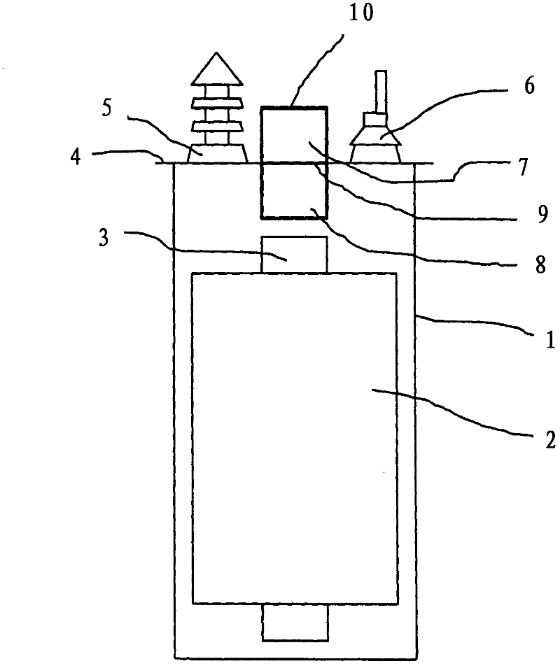
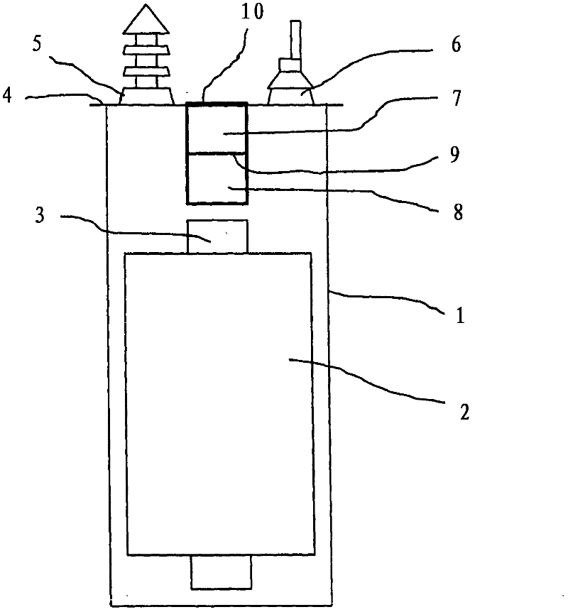
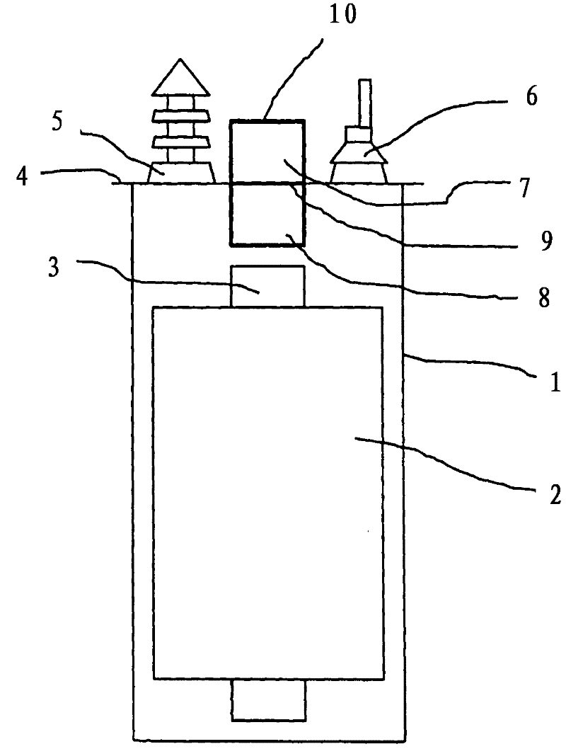
[0018] exist figure 1 The tank 1 of the regulating transformer is shown in schematic diagram in the interior of the tank 2 and at least one iron yoke 3 are located. The tank 1 is closed at the top by a transformer cover 4 . Typically, the complete tank 1 is filled with oil. Also shown above the transformer cover 4 are MS insulating bushings 5 ​​and NS insulating bushings 6 . The connection to the primary or secondary side of the winding 2 inside the transformer and the electrical connection of the regulating winding to the adjustable converter are not shown. An adjustable converter is arranged above the iron yoke 3, and the adjustable converter has an electronic on-load switch 7 and a mechanical contact system 8 and a selector below it. The on-load switch 7 and the contact system 8 are gas-tightly separated from each other by a horizontal feed-through plate 9 . The electrical connection of the two parts of the adjustable converter through the feed-through plate 9 is also n...


PUM


Abstract

The invention relates to the arrangement of a stepping switch on a control transformer, wherein either only the mechanical contact system (8) of the stepping switch or also its load changeover switch (7) is or are arranged within the tank (1) of the transformer, under the transformer cover (4) and above the iron yoke (3).

Description

technical field [0001] The invention relates to a system for the arrangement of adjustable converters, in particular electronically adjustable converters, on regulating transformers, in particular distribution transformers. Background technique [0002] Adjustable converters are used to switch between winding taps of a regulating transformer without interruption. Such adjustable converters have been in the state of the art for many years and are known in many embodiments with mechanical contacts or vacuum switching tubes or also semiconductor converters as switching elements for on-load switching. [0003] by public document" On-Load Tap-Changers for Power Transformers" MR-Publication, 2000, p. 6, Different known arrangements of known tap-changers on or in transformers. type converter), the adjustable converter is completely immersed in the transformer tank and is located laterally beside the transformer winding and is surrounded by its oil volume. Depending on the design...

Claims


Application Information

Patent Timeline
IPC IPC(8): H01H9/00H01F27/40
CPCH01H9/0044H01F27/40H01F29/04H01H9/0005
Inventor O·布吕克尔D·多纳尔
Owner MASCHFAB REINHAUSEN GEBR SCHEUBECK GMBH & CO KG
Learn More