
Lamp tube bending process and bending mechanism

A lamp and bending technology, which is applied in the field of lamp bending method and bending mechanism, can solve the problems of excessive requirements, lengthening the length of both ends of the lamp, and increasing tube consumption, so as to ensure the quality of the bend and reduce the Transmission process, the effect of reducing amplification errors

Inactive Publication Date: 2012-05-30
上海良才机电科技开发有限公司
View PDF11 Cites 0 Cited by
  • Summary
  • Abstract
  • Description
  • Claims
  • Application Information

AI Technical Summary

Problems solved by technology

However, these prior art techniques or devices have the following major problems. One is that the lamp tube heated to a molten state is taken out by the clamp and transferred to the forming mold. The process is not stable, resulting in low yield and difficult improvement of lamp quality. The second is that the mechanism is complicated, and the error of each step is multiplied due to multiple motions and superposition, and the requirements for the mechanism control program and parameter settings are too high; the third is to lengthen the lamp for counterweight or clamping the lamp. The length of both ends of the tube increases the consumption of the tube and increases the production cost; the fourth is that the heating method is not conducive to obtaining a suitable bending preform of the lamp tube
Due to the existence of these problems, it is necessary to bend the lamp tube with a large forming area, especially to achieve a more complex curve bending effect, or for the lamp tube with a short straight length (such as less than 10 mm) and shorter lamp tubes processing, which is difficult to complete in practice

Method used


Image

  • Lamp tube bending process and bending mechanism
  • Lamp tube bending process and bending mechanism
  • Lamp tube bending process and bending mechanism

Examples


Embodiment Construction

[0013] Below in conjunction with accompanying drawing and specific embodiment the utility model is described in further detail:

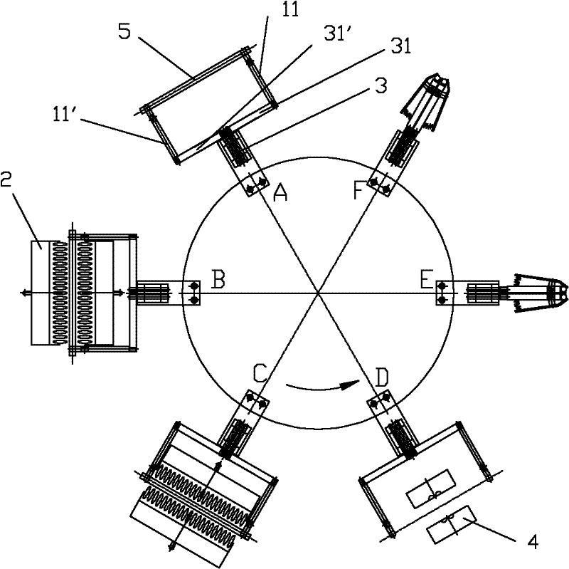
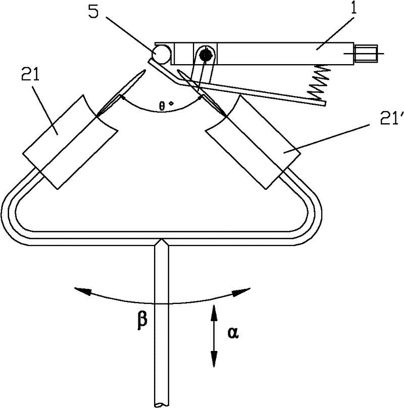
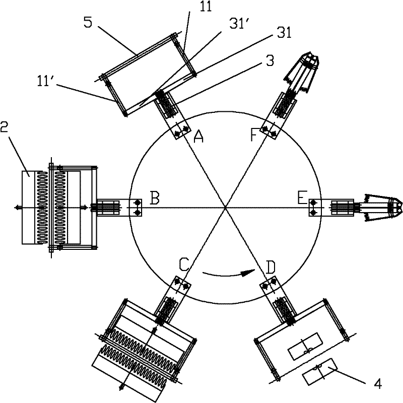
[0014] as attached figure 1 , the lamp tube bending mechanism of the present invention includes a burner 2, a bending device 3, a forming device 4, and a clamp 1; wherein the bending device 3 can be rotated and shifted in a gap, and can be in six positions: A, B, C, D, E, and F. Station, the bending device 3 is provided with bending arms 31, 31', and two clamps 11, 11' are respectively fixed on the bending arms 31, 31' to clamp the two ends of the lamp tube 5; the burner 2 for melting and softening the lamp tube is located The periphery of the lamp tube can also rotate around the lamp tube. The burner 2 has an array, and is located side by side at the periphery of the lamp tube 5 respectively. figure 2 As shown, each group of fire heads is composed of two fire heads 2, which are vertically arranged with the lamp tube 5, and can move radially close...


PUM


Abstract

The invention discloses a lamp tube bending process, comprising the following procedures that: a clamp fixed on an elbow device clamps the two ends of a lamp tube to be processed so that the lamp tube cannot revolve on axis per se and move axially; the lamp tube is melted down through a fire head which moves according to preset procedures; the lamp tube after being softened is released from the fire head and is bent and a pre-shaped through the elbow device; and the pre-shaped lamp tube enters into a shaping device to be shaped. A lamp tube bending mechanism used for the process is also disclosed. According to the lamp tube bending process and the lamp tube bending mechanism disclosed by the invention, the lamp tube with a big shaping region can be bent, and tube consumption can also be reduced greatly. In addition, a relatively complex curve bending effect can be realized. The lamp tube bending process and the lamp tube bending mechanism disclosed by the invention can be widely applied to lamp tube processing.

Description

technical field [0001] The invention relates to the technical field of lamp tube processing, more specifically, it relates to a lamp tube bending method and a bending mechanism. Background technique [0002] Since the appearance of energy-saving lamps, they have been widely loved by people because of their energy-saving effects. At present, the shape of energy-saving lamp tubes is mainly developed in the direction of high efficiency, energy saving and aesthetic appearance. Spherical lamps and plum blossom lamps produced by the combination of space curve lamp tubes through the bridging process represent this development direction. Because these lamp tubes have a large range of forming areas, the range in which the straight glass tubes need to be heated is correspondingly larger. Existing lamp tube bending mostly adopts the linear rolling conveying device described in CN1528690 to transport the lamp tubes, and completes the heating of the lamp tubes during the conveying proce...

Claims


Application Information

Patent Timeline
Patent Type & Authority Applications(China)
IPC IPC(8): C03B23/06C03B23/045
Inventor 薛良才吴秀兰
Owner 上海良才机电科技开发有限公司
Learn More