
Numerical-control feed clamp

A fixture and feeding technology, applied in metal processing and other directions, to achieve the effects of precision processing, strong automation and reasonable structure

Inactive Publication Date: 2014-08-27
浙江盛业科技有限公司
View PDF7 Cites 0 Cited by
  • Summary
  • Abstract
  • Description
  • Claims
  • Application Information

AI Technical Summary

Problems solved by technology

[0002] In the processing of electrical parts and glasses parts, the processing of granular objects such as wire terminals and glasses hinges requires cutting and milling of linear workpieces to complete; because wire terminals and glasses hinges are processed At the same time, their blanks to be processed have a specified length. Therefore, when cutting the linear workpiece into granular workpieces, it is necessary to use numerical control technology to control the length of the linear body moving in the feeding chute. Obviously , using the existing common feeding device, such as the cooperation between the feeding trough and the ejector pin, cannot complete this work well, so it is necessary to carry out an innovative design on the basis of the existing feeding device

Method used


Image

  • Numerical-control feed clamp
  • Numerical-control feed clamp
  • Numerical-control feed clamp

Examples


Embodiment Construction

[0018] Embodiment of the present invention is illustrated below in conjunction with accompanying drawing:

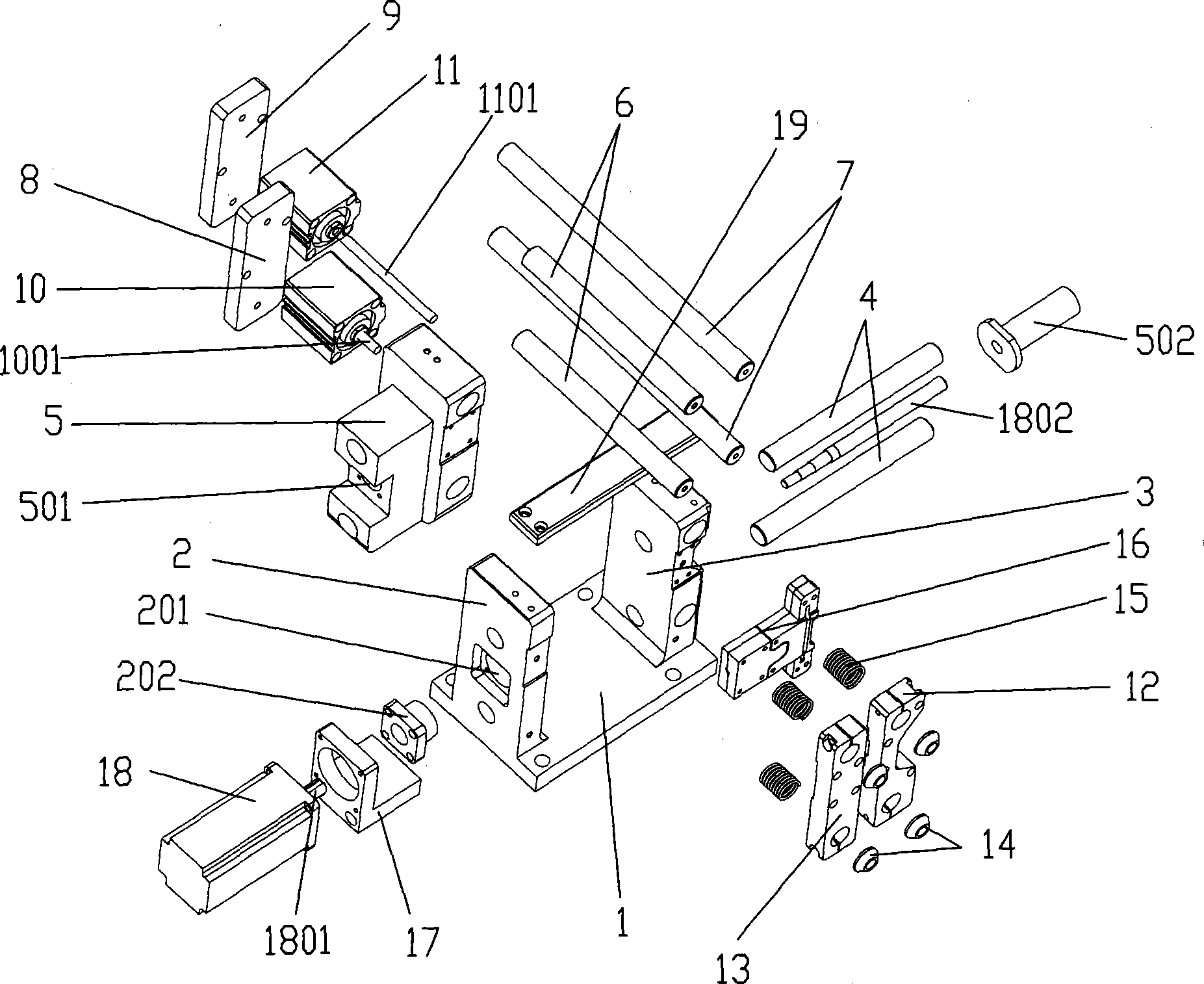
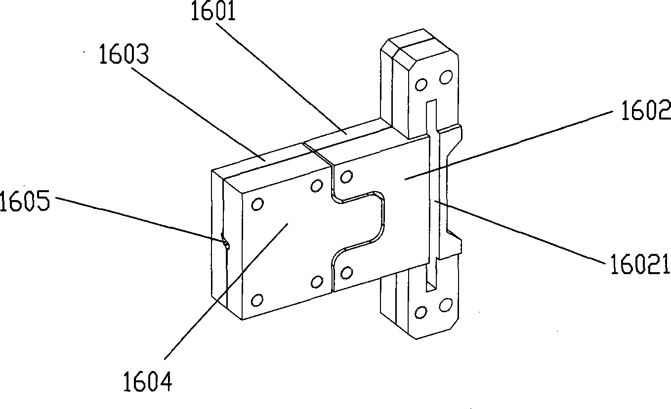
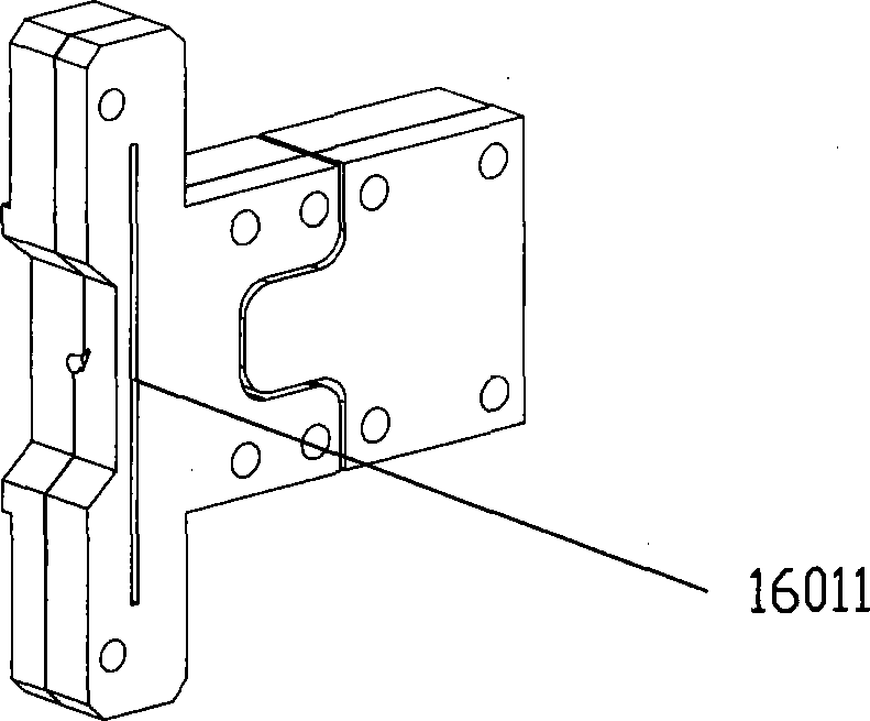
[0019] Provide a kind of numerical control feeding fixture, there is a workbench 1, the first column 2 and the second column 3 are arranged on the workbench 1, the first column 2 and the second column 3 are connected by two first guide rails 4, the first Between the column 2 and the second column 3, there is a slider assembly 5 that cooperates with the two first guide rails 4. The second guide rail 6 at the end, two second guide rails 6 one ends are connected by the first fixed block 8, the first cylinder 10 is arranged on the first fixed block 8; The third guide rail 7 positioned at the upper and lower ends of the second column 3, one end of the two third guide rails 7 are connected by the second fixed block 9, and the second fixed block 9 is provided with a second cylinder 11; a clamp 16 is formed by the clamping die head and The clamping base is butted, and the clamp...


PUM


Abstract

The invention relates to a numerical-control feed clamp. The numerical-control feed clamp consists of a clamp die head and a clamp die holder which are in butted joint with each other, wherein the clamp die head consists of a clamp die head first substrate and a clamp die head second substrate; the clamp die holder consists of a clamp die holder first substrate and a clamp die holder second substrate; and after the clamp die head and the clamp die holder are matched, a feed chute for linear workpieces is formed; the first substrate of the clamp die head is fixed on a second upright on a workbentch, the second substrate of the clamp die holder is fixed on a first cover plate; the first substrate of the clamp die holder is fixed on a sliding block assembly of the workbentch, the second substrate of the clamp die holder is fixed on a second cover plate; the first cover plate is connected to a head of a third guide rail and is fixed by a handle cap, the second cover plate is connected to the head of a second guide rail and is fixed by the handle cap; a lead screw head fixed seat and a sever motor base which are in the same direction with the first guides rail and arranged between two first guide rails are arranged on the first upright, after the lead screw head and the sever motor base are fixed on the first upright, an output shaft of the sever motor is coaxially connected to a lead screw, then the lead screw is movably connected to the sliding block assembly through a lead screw pulley and sliding block assembly, and drives the sliding block assembly to move to and fro on the first guide rails. By adopting the numerical control technique, the invention has the characteristics of reasonable structure, high integration level, high automation degree and precise processing.

Description

technical field [0001] The invention relates to the field of industrial clamps, in particular to a clamp. Background technique [0002] In the processing of electrical parts and glasses parts, the processing of granular objects such as wire terminals and glasses hinges requires cutting and milling of linear workpieces to complete; because the processing of wire terminals and glasses hinges , their blanks to be processed have a specified length. Therefore, when the linear body workpiece is cut into granular workpieces, it is necessary to control the length of the linear body moving in the feeding trough sequentially through numerical control technology. Obviously , using the existing common feeding device, such as the cooperation of the feeding trough and the ejector pin, cannot complete this work well, so it is necessary to carry out innovative design on the basis of the existing feeding device. Contents of the invention [0003] The object of the present invention is to ...

Claims


Application Information

Patent Timeline
Patent Type & Authority Patents(China)
IPC IPC(8): B26D7/06
Inventor 杨兴龙杨小龙
Owner 浙江盛业科技有限公司
Learn More