Integratedly designed rotary compressor structure
A compressor and rotor-type technology, applied in the field of rotor-type compressor structure, can solve the problems of reduced working efficiency of the compressor, difficulty in ensuring coaxiality, and influence on compressor performance, etc., achieve uniform clearance, and solve the problem that the coaxiality is not easy to guarantee , the effect of good coaxiality
- Summary
- Abstract
- Description
- Claims
- Application Information
AI Technical Summary
Problems solved by technology
Method used
Image

Examples
Embodiment 1
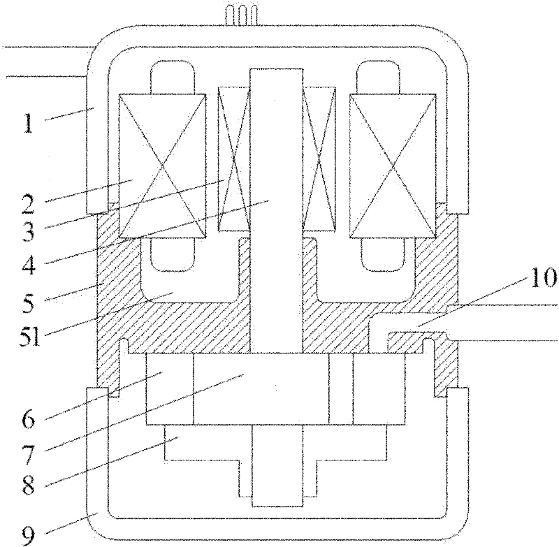
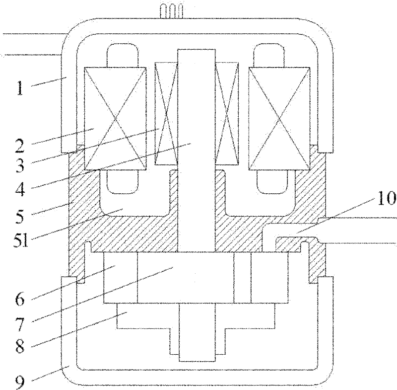
[0018] like figure 1 As shown, the integrated design of the rotor compressor structure includes an upper shell cover 1, a stator 2, a rotor 3, a crankshaft 4, an integrated frame 5, a cylinder 6, a piston 7, a lower cylinder cover 8, and a lower shell cover 9. The air intake connecting pipe 10, the upper part of the integrated frame 5 is connected with the upper shell cover 1, and the lower part is connected with the lower shell cover 9, and fixed by laser welding. The upper part of the integrated frame 5 is provided with a ring Groove 51, the bottom of stator 2 falls in annular groove 51, crankshaft 4 and piston 7 are integrated, integral frame 5 is by metal material, such as cast iron (FC250) by one-shot molding.
Embodiment 2
[0020] see figure 1 , an integrally designed rotor compressor structure, wherein the upper part of the integrated frame 5 is connected to the upper casing cover 1, and its lower part is connected to the lower casing cover 9 and fixed by glue, and the rest of the structure is the same as that of the embodiment 1 is the same.
PUM
 Abstract
Description
Claims
Application Information